OPERATOR’S MANUAL 3000 TRACTOR Model 3235 IMPORTANT: READ SAFETY RULES AND INSTRUCTIONS CAREFULLY Warning: This unit is equipped with an internal combustion engine and should not be used on or near any unimproved forest-covered, brush-covered or grass-covered land unless the engine’s exhaust system is equipped with a spark arrester meeting applicable local or state laws (if any). If a spark arrester is used, it should be maintained in effective working order by the operator.
TABLE OF CONTENTS PAGE TRACTOR PREPARTION . . . . . . . . . . . . . . . . . . . . . . . . . . . . . . . . . . . . . . 2 IMPORTANT SAFE OPERATION PRACTICES . . . . . . . . . . . . . . . . . . . . . 3 CALLING SERVICE INFORMATION . . . . . . . . . . . . . . . . . . . . . . . . . . . . . . 7 FINDING YOUR MODEL & SERIAL NUMBER . . . . . . . . . . . . . . . . . . . . . . 7 SAFETY LABELS FOUND ON YOUR UNIT . . . . . . . . . . . . . . . . . . . . . . . . 8 CONTROLS . . . . . . . . . . . . . . . . . . . . . . . . .
SECTION 2: IMPORTANT SAFE OPERATION PRACTICES WARNING: THIS SYMBOL POINTS OUT IMPORTANT SAFETY INSTRUCTIONS WHICH, IF NOT FOLLOWED, COULD ENDANGER THE PERSONAL SAFETY AND/OR PROPERTY OF YOURSELF AND OTHERS.READ AND FOLLOW ALL INSTRUCTIONS IN THIS MANUAL BEFORE ATTEMPTING TO OPERATE YOUR UNIT. FAILURE TO COMPLY WITH THESE INSTRUCTIONS MAY RESULT IN PERSONAL INJURY. WHEN YOU SEE THIS SYMBOL, HEED ITS WARNING.
• Never leave a running machine unattended. Always turn off blade(s), place transmission in neutral, set park brake, stop engine and remove key before dismounting. • Your mower is designed to cut normal residential grass of a height no more than 10". Do not attempt to mow through unusually tall, dry grass (e.g., pasture) or piles of dry leaves. Debris may build up on the mower deck or contact the engine exhaust presenting a potential fire hazard. • Turn off blade(s) when not mowing.
• Use extra care with grass catchers or other attachments. These can change the stability of the machine. • Before and when backing, look behind and down for small children. • Never carry children, even with the blades off. They may fall off and be seriously injured or interfere with the safe machine operation. • Keep all movement on the slopes slow and gradual. Do not make sudden changes in speed or direction.
• To reduce fire hazard, keep the machine free of grass, leaves or other debris build-up. Clean up oil or fuel spillage. Allow machine to cool at least 5 minutes before storing. • Check brake operation frequently. Adjust and service as required. • Muffler, engine and belt guards become hot during operation and can cause a burn. Allow to cool down before touching. • Before cleaning, repairing or inspecting, make certain the blade and all moving parts have stopped.
SECTION 3: CALLING SERVICE INFORMATION The engine manufacturer is responsible for all engine-related issues with regards to performance, power-rating, and specifications. If you have difficulties with the unit, have any question regarding the operation or maintenance of this equipment, or desire additional information not found in this manual, contact your dealer.
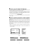
SECTION 5: SAFETY LABELS FOUND ON YOUR UNIT WARNING DECK HEIGHT ADJUSTMENT AVOID SERIOUS INJURY OR DEATH (360 Turn Equals 1/2" Adjustment) 1.RAISE DECK LIFT LEVER UNTIL THE NUMBER 6 APPEARS IN WINDOW. • GO UP AND DOWN S L O P E S, N OT A C R O S S. • AVO I D S U D D E N T U R N S. • POSITION INDICATOR • 2.TURN KNOB COUNTER CLOCKWISE TO LOWER DECKSTOP. • • 3. TURN KNOB CLOCKWISE TO RAISE DECKSTOP. 4. LOWER DECK LIFT LEVER UNTIL POSITION INDICATOR STOPS. • 5. REPEAT PROCESS IF NECESSARY.
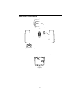
SECTION 6: CONTROLS Figure 3 9
NOTE: References to LEFT and RIGHT indicate that side of the tractor when facing forward while seated in the drivers seat. Reference to FRONT indicates the grille end of the tractor; to REAR, the drawbar end. switch when starting the tractor. Depressing the brake pedal will also engage the transmission differential lock. Always make certain the diff. lock disengages when the brake pedal is released.
Ignition / Light Switch Cup Holder To prevent accidental starting and/or battery discharge, remove the key from the ignition switch when the tractor is not in use. The combination lights and ignition switch has four positions. See Figure 8 for a description of each position. The cup holder is located on the fender to the left of the seat. Hydraulic Lift Lever The hydraulic lift lever is located on the fender to the left of the seat. This lever is used to operate the tractor’s center lift system.
Seat Adjustment Lever The seat adjustment lever is located below the seat. This lever is used to adjust the seat forward or backward. LOWER Differential Lock Pedal Located at the front of the left running board. Depressing the diff. lock pedal engages the transmission differential lock, which improves traction at the rear wheels when operating on uneven terrain or in slippery conditions. However, use care when engaging the diff. lock on manicured turf where sharp turns are required.
Indicator Light Pod A B D E C A Oil Pressure Indicator B Low Fuel Indicator C Hour Meter D Not Used E Not Used Figure 12 Hour Meter The hour meter is part of the indicator light pod in the dash panel. The hour meter operates whenever the ignition switch is in the “ON” or “ON/LIGHTS” position. Record the actual hours of tractor operation to ensure all maintenance procedures are completed according to the schedule in this manual.
SECTION 7: OPERATION Safety Interlock Switches This tractor is equipped with a safety interlock system for the protection of the operator. If the interlock system should ever malfunction, do not operate the tractor. Contact your authorized Cub Cadet Dealer. The safety interlock system prevents the engine from cranking or starting unless the brake pedal is fully depressed, and the PTO is “OFF”.
• Place the PTO switch in the “OFF” position. Place the throttle control lever between the “MID” and “FAST” positions. Then turn the ignition key to the “OFF” position and remove the key from the ignition switch. Driving The Tractor WARNING: Avoid sudden starts, excessive speed and sudden stops. WARNING: Do not leave the seat of the tractor without disengaging the PTO and engaging the parking brake. If leaving the tractor unattended, turn the ignition key off and remove key.
Avoid stopping when driving up a slope. If it is necessary to stop while driving up a slope, start up smoothly and carefully to reduce the possibility of flipping the tractor over backward. Stopping The Tractor Fully depress the brake pedal to bring the tractor to a complete stop, engage the parking brake, disengage the PTO, turn the ignition switch to “OFF’” and remove the key from the switch before dismounting.
For best results it is recommended that the first two laps should be cut with the discharge thrown towards the center. After the first two laps, reverse the direction to throw the discharge to the outside for the balance of cutting. This will give a better appearance to the lawn. Do not cut the grass too short, as the mower will tend to scalp the grass. Short grass invites weed growth and yellows quickly in dry weather. Mowing should be done with the engine at full throttle. Do not mow at high ground speed.
For the comfort of the operator, this tractor is equipped with an adjustable tilt steering wheel. To adjust the steering wheel: push the steering wheel tilt lock lever downward, move the steering wheel to the desired position, and release the steering wheel tilt lock lever. Front Wheel Alignment Note: The left-hand ball joint is lefthand threaded. The front wheels should toe-in approximately 1/8 inch. Measure distances A and B. A should be approximately 1/8 inch less than B. See Figure 16.
From just above the right axle carrier, inside the right frame rail, slowly turn the hex nylon lock nut at the end of the brake rod as follows to adjust the brake (Refer to Figure 18): • Turn the nylon lock nut clockwise to increase the braking force. • Turn the nylon lock nut counterclockwise to decrease the braking force. Recheck the brake adjustment to ensure proper operation, and readjust as necessary. If brake adjustment does not correct the problem, see your authorized Cub Cadet dealer.
LUBRICATION ILLUSTRATION Transmission 20 L/R Front Wheels Foot Control Pivot Points Engine Oil Can (High quality lubricating oil) Front Pivot Axle Engine Oil: See Figure 27 on page 30 Transmission Oil - Cub Cadet Drive System Fluid Plus - ONLY L/R Steering Knuckle Cub Cadet 251H EP Grease or equivalent No.
Accessing Engine Compartment The engine compartment can be accessed by raising the hood as follows: • Lift the hood straight upward at the recessed notches of the side panels to disengage the internal hood latch. • Carefully pivot the hood forward to open. To close the hood: • Carefully pivot the hood rearward to lower. • Push down on the front of the hood to engage the internal hood latch. If greater access is required, the tractor is equipped with quick release side panels.
• • • • • • immediately with clean cold water. If there is any further discomfort, seek prompt medical attention. If acid spills on clothing, first dilute it with clean water, then neutralize with a solution of ammonia/water or baking soda/water. Since battery acid is corrosive, do not pour it into any sink or drain. Before discarding an empty electrolyte container, rinse it thoroughly with a neutralizing solution.
Headlight Bulb Replacement Replace headlight bulbs as follows: (See Figure 20) 1. After noting which wire connects to each terminal, unplug the wire harness leads from the headlight socket terminals. 2. Rotate the socket assembly as follows to remove from the reflector housing: Socket Tab Terminals Socket Reflector Housing NOTE: Because of the close proximity of the fuel tank, caution should be taken when removing the tail light sockets from the reflector housings.
must be withdrawn and wiped clean, then fully reinserted before being withdrawn again for a true reading. Dipstick Reading F Operating Range A • Remove the dipstick from the oil fill tube and SLOWLY pour oil into the oil fill tube. Fill the transmission case until the oil level reaches the “FULL” mark on the dipstick. • Reinstall the dipstick securely into the oil fill tube.
Oil Filter Transmission Drain Plug Figure 22 • Clean around the base of the transmission oil filter and remove the filter by turning it counterclockwise. • Apply a light coating of clean transmission oil to the gasket of the new filter. Install the filter by turning it clockwise, by hand, until the gasket contacts the filter base on the transmission housing; then tighten the filter an additional 1/2 turn.
• Add to clean, fresh gasoline the correct amount of stabizer for the capacity of the fuel system. Fuse Fuses are installed to protect the tractor’s electrical system from damage caused by excessive amperage. Always use the same capacity fuse for replacement. Refer to the Specifications Chart. If the electrical system does not function, check the fuses. To replace a fuse, note the position of the fuse and pull the old fuse from the electical box.
SECTION 10: ENGINE INFORMATION KOHLER CO. FEDERAL AND CALIFORNIA EMISSION CONTROL SYSTEMS LIMITED WARRANTY SMALL OFF-ROAD EQUIPMENT ENGINES The U.S. Environmental Protection Agency (EPA), the California Air Resources Board (CARB), and Kohler Co. are pleased to explain the Federal and California Emission Control Systems Warranty on your small off-road equipment engine. For California, engines produced in 1995 and later must be designed, built and equipped to meet the state’s stringent anti-smog standards.
LIMITATIONS This Emission Control System Warranty shall not cover any of the following: (a) repair or replacement required because of misuse or neglect, improper maintenance, repairs improperly performed or replacement not conforming to Kohler Co. specifications that adversely affect performance and/or durability, and alterations or modifications not recommended or approved in writing by Kohler Co.
Cleaning The Engine This tractor has an air-cooled engine. Air must be able to circulate freely around the engine through the flywheel screen, through the cooling shrouds and over the fins of the cylinder head and cylinder block. Keep these areas free of accumulated dirt and debris or the engine will overheat; possibly causing extensive engine damage. Regularly clean the inside of the side panels, dash intake screen and grille to ensure adequate cooling.
Refer to Figure 27 for information regarding the proper type of oil to add to the crankcase. • Place the tractor on a level surface and engage the parking brake. Stop the tractor engine and remove the ignition key. • Clean the area around the oil filler cap to prevent debris from entering the crankcase. See Figure 26. • Remove the oil filler cap from the left valve cover and SLOWLY pour in oil. Fill the crankcase until the oil level reaches the “FULL” mark on the dipstick. See Figure 25.
• Attach the flexible tubing to the drain valve. Place an appropriate container below the open end of the tubing to collect the old oil. • To open the drain valve, push it slightly inward and turn it counterclockwise until it stops, then pull it outward. • Remove the filter by turning it counterclockwise using an automotive type filter wrench to loosen. • Allow the old oil to completely drain from the engine crankcase into the container below.
WARNING: Operating the engine with loose or damaged air cleaner components will allow unfiltered air into the carburetor, causing extensive wear and eventual failure of the engine. Servicing The Precleaner Wash and re-oil the foam precleaner more often under extremely dusty or dirty conditions. See Figure 29. • Loosen the aircleaner cover knob and remove the cover. • Remove the foam precleaner by sliding it up off the paper element. • Wash the precleaner in warm water with detergent.
SECTION 11: TROUBLE SHOOTING Possible Cause Possible Remedy Hard To Start No fuel in fuel tank or carburetor Fill the tank with fuel. Check the fuel line, carburetor and fuel filter. Fuel ine or carburetor clogged Clean the fuel line and carburetor with a commercial carburetor cleaner. Fuel filter plugged Replace Water in fuel Drain the fuel tank and carburetor. Use new fuel and dry the sparks plugs. Choked improperly.
Possible Cause Possible Remedy Fuel tank air vent clogged Remove obstruction from the vent in the fuel tank cap. Air leakage between carburetor and engine Remove air cleaner. Tighten the carburetor and manifold mounting hardware. Replace any damaged parts as indicated in “MAINTENANCE.” Incorrect timing or faulty ignition See your authorized dealer. Brake dragging Adjust the brakes. Refer to “ADJUSTMENTS.
SECTION 12: OPTIONAL EQUIPMENT When you purchased your tractor, you probably had it completely equipped for your particular needs at that time. However, later you may wish to obtain optional equipment or accessories. These items and other allied equipment can be purchased from, and installed by, your authorized Cub Cadet dealer.
SECTION 13: SPECIFICATIONS Engine Manufacturer . . . . . . . . . . . . . . . . . . . . . . . . . . . . . . . . . . . . . . . . . Kohler Horsepower . . . . . . . . . . . . . . . . . . . . . . . . . . . . . . . . . . . . . . . . . . . . . 25 Cylinders . . . . . . . . . . . . . . . . . . . . . . . . . . . . . . . . . . . . . . 2 (Command) Cooling . . . . . . . . . . . . . . . . . . . . . . . . . . . . . . . . . . . . . . . . . . . . . . . . Air Fast Idle Speed . . . . . . . . . . . . . . . . . . . . . . . . .
SECTION 14: SLOPE GAUGE WARNING: Do not mow on inclines with a slope in excess of 15 degrees (a rise of approximately 2-1/2 feet every 10 feet). A riding mower could overturn and cause serious injury. If operating a walkbehind mower on such a slope, it is extremely difficult to maintain your footing and you could slip, resulting in serious injury. • Operate RIDING mowers up and down slopes, never across the face of slopes. • Operate WALK-BEHIND mowers across the face of slopes, never up and down slopes.
CUB CADET LLC MANUFACTURER’S ONE YEAR LIMITED WARRANTY (COMMERCIAL USE) The limited warranty set forth below is given by CUB CADET LLC (“CUB CADET”) with respect to new merchandise purchased and used in the United States, its possessions and territories.
The provisions as set forth in this Warranty provide the sole and exclusive remedy arising from the sale.
CUB CADET LLC MANUFACTURER’S LIMITED WARRANTY (RESIDENTIAL USE) The limited warranty set forth below is given by CUB CADET LLC (“CUB CADET”) with respect to new merchandise purchased and used in the United States, its possessions and territories.
This limited warranty does not provide coverage in the following cases: a. Routine maintenance items such as lubricants, filters, blade sharpening and tune-ups, or adjustments such as brake adjustments, clutch adjustments or deck adjustments; and normal deterioration of the exterior finish due to use or exposure. b.
SECTION 15: QUICK REFERENCE PARTS Description Part Number Engine Oil 737-3030A (10W30) 737-3049 (5W30) Air Filter CARTRIDGE FOAM PRE-CLEANER KH-47-083-03 KH-24-083-02 Engine Oil Filter KH-12-050-08 Spark Plug 759-3336 Transmission Oil Cub Cadet Drive System Fluid Plus 737-3120 - Quart 737-3121 - Gallon Transmission Oil Filter 923-3014 Mower Deck Blades Mower Deck Belts PTO Belt (set of 2) 44” Deck -759-3939 (3) 48” Deck -759-3826 (3) 54” Deck -759-3820 (3) 60” Deck -759-3809 (3) 44” Deck - 95