Safety • Assembly • Operation • Adjustments • Maintenance • Troubleshooting • Parts Lists • Warranty OPERATOR’S MANUAL Two-Stage Snow Thrower IMPORTANT: READ SAFETY RULES AND INSTRUCTIONS CAREFULLY BEFORE OPERATION PRINTED IN U.S.A.
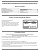
This Operator’s Manual is an important part of your new snow thrower. It will help you assemble, prepare and maintain the unit for best performance. Please read and understand what it says. Table of Contents Safety Labels....................................................... 3 Safe Operation Practices.................................... 4 Setting Up Your Snow Thrower........................... 6 Operating Your Snow Thrower.......................... 10 MakingAdjustments.....................................
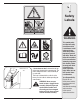
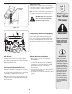
1 Safety Labels WARNING #3 Chute Clean-out Tool A chute clean-out tool is fastened to the top of the auger housing with a mounting clip. The tool is designed to clear a chute assembly of ice and snow. This item is fastened with a cable tie at the factory. Cut the cable tie before operating the snow thrower. WARNING: Never use your hands to clear a clogged chute assembly.
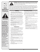
2 Safe Operation Practices WARNING This symbol points out important safety instructions which, if not followed, could endanger the personal safety and/or property of yourself and others. Read and follow all instructions in this manual before attempting to operate this machine. Failure to comply with these instructions may result in personal injury.
Operation Maintenance & Storage 1. Do not put hands or feet near rotating parts, in the auger/impeller housing or chute assembly. Contact with the rotating parts can amputate hands and feet. 2. The auger/impeller control lever is a safety device. Never bypass its operation. Doing so makes the machine unsafe and may cause personal injury. 3. The control levers must operate easily in both directions and automatically return to the disengaged position when released. 4.
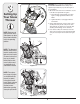
3 Setting Up Your Snow Thrower IMPORTANT: The snow thrower is shipped with oil and WITHOUT GASOLINE. After assembly, refer to separate engine manual for proper fuel and engine oil recommendations. 1. Observe the lower area of the snow thrower to be sure both cables are aligned with roller guides. a. Pull up and back on upper handle as shown in Figure 3-1. Align upper handle with the lower handle. A B b. Tighten hand knobs securing upper handle to lower handle. 2.
3 4. Finish securing chute control assembly to chute support bracket with wing nut and hex screw removed earlier. See Figure 3-4. Setting Up Your Snow Thrower Figure 3-4 CAUTION Prior to operating your snow thrower, refer to Auger Control Test on page 13. Read and follow all instructions carefully and perform all adjustments to verify your unit is operating safely and properly. 5. Check that all cables are properly routed through the cable guide on top of the engine. See Figure 3-5.
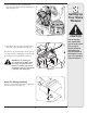
3 Drift Cutters (If Equipped) Drift cutters should be used when operating the snow thrower in heavy drift conditions. • On models so equipped, drift cutters and hardware are assembled to the auger housing inverted. See Figure 3-7. Setting Up Your Snow Thrower • Remove the carriage bolts and wingnuts securing the drift cutters to the housing. • Reposition drift cutters so they face forward as shown in Figure 3-8.
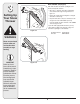
Clean-Out Tool Clean-Out Tool The clean-out tool is mounted to the rear of the auger housing and is designed to clear a clogged chute. Refer to page 11 for instructions on how to properly use it. NOTE: This item is fastened with a cable tie to the rear of the auger housing at the factory. Cut the cable tie before operating the snow thrower. WARNING: Never use your hands to clean snow and ice from the chute assembly or auger housing.
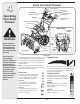
4 Operating Your Snow Thrower Know Your Snow Thrower Drive Control Shift Lever Four-Way Chute Control™ Auger Control Heated Handles Switch (en option)† Headlight Wheel Steering Control † Electric Start Button Gas Cap Oil Fill Engine Controls Recoil Starter Handle Electric Starter Outlet Primer Ignition Key WARNING Read, understand, and follow all instructions and warnings on the machine and in this manual before operating. Use extreme care when handling gasoline.
Auger Control • To change the direction in which snow is thrown, squeeze the button on the joy-stick and pivot the joy-stick to the right or to the left. !5'%2 #/.42/, • To change the angle/distance which snow is thrown, pivot the joy-stick forward or backward. Wheel Steering Controls '/ The auger control is located on the left handle. Squeeze the control grip against the handle to engage the augers and start snow throwing action. Release to stop. Drive Control/ Auger Control Lock $2)6% #/.
4 Gas & Oil Fill-Up Service the engine with gasoline and oil as instructed in the separate engine manual packed with your unit. Read instructions carefully. Starting The Engine 1. Attach spark plug wire to spark plug. Make certain the metal loop on the end of the spark plug wire (inside the rubber boot) is fastened securely over the metal tip on the spark plug. 2. Make certain both the auger control and drive control are in the disengaged (released) position.
NOTE: Keep the key in a safe place. The engine cannot start without the ignition key. Recoil Starter 1. With engine running, pull starter rope with a rapid, continuous full arm stroke three or four times. Pulling the starter rope will produce a loud clattering sound, which is not harmful to engine. 2. Move throttle control to STOP position. 3. Remove the ignition key (Do not turn key) to prevent unauthorized use of equipment. NOTE: Keep the key in a safe place.
5 Shift Cable If the full range of speeds (forward and reverse) cannot be achieved, refer to the figure to the left and adjust the shift cable as follows: 1. Place the shift lever in the fastest forward speed position. Making Adjustments 2. Loosen the hex nut on the shift cable index bracket. See Figure 5-1. 3. Pivot the bracket downward to take up slack in the cable. 4. Retighten the hex nut. 5. Check for correct adjustment before operating the snow thrower.
5 2. With the drive control released, there must be 1/8” clearance between the friction wheel and the drive pulley in all positions of the shift lever. 3. With the drive control engaged, the friction wheel must contact the drive pulley. See Figure 6-8. 4. If adjustment is necessary, loosen the lower hex nut on the drive cable index bracket and pivot the bracket upward or downward as necessary. Refer to Figure 5-3. Tighten the lower hex nut to secure the bracket when correct adjustment is reached.
6 Maintaining Your Snow Thrower Engine Refer to the separate engine manual packed with your unit for all engine maintenance. Lubrication Engine Refer to the separate engine manual packed with your unit for all engine lubrication instructions. Gear Shaft The gear (hex) shaft should be lubricated at least once a season or after every 25 hours of operation. 1. Carefully pivot the snow thrower up and forward so that it rests on the auger housing. 2.
Auger Belt Replacement To remove and replace your snow thrower’s auger belt, proceed as follows: 1. Remove the plastic belt cover on the front of the engine by removing the two self-tapping screws. See Figure 6-4. NOTE: Drain the gasoline from the snow thrower, or place a piece of plastic under the gas cap. 2. Carefully pivot the snow thrower up and forward so that it rests on the auger housing.
6 Maintaining Your Snow Thrower NEVER replace the auger shear pins with standard hex pins. Any damage to the auger gearbox or other components as a result of failing to do so will NOT be covered by your snow thrower’s warranty. Drive Belt Replacement To remove and replace your snow thrower’s auger belt, proceed as follows: 1. Remove the plastic belt cover on the front of the engine by removing the two self-tapping screws. See Figure 6-4. c b 2.
Observe the following, when preparing your snow thrower for off-season storage: • Drain fuel into an approved container outdoors, away from any open flame. Allow engine to cool. Extinguish cigarettes, cigars, pipes and other sources of ignition prior to draining fuel. Fuel left in engine during warm weather deteriorates and will cause serious starting problems. • If unit is to be stored over 30 days, prepare for storage as instructed in the separate engine manual packed with your unit.
8 Problem Cause Remedy 1. Choke not in ON position. 1. Move choke to ON position. 2. Spark plug wire disconnected. 2. Connect wire to spark plug. 3. Fuel tank empty or stale fuel. 3. Fill tank with clean, fresh gasoline. 4. Engine not primed. 4. Prime engine as instructed in “Operating Your Snow Thrower”. 5. Faulty spark plug. 5. Clean, adjust gap, or replace. 6. Blocked fuel line. 6. Clean fuel line. 7. Safety key not in ignition on engine. 7. Insert key fully into the switch. 8.
THREE (3) YEAR LIMITED WARRANTY For three (3) years from the date of original purchase of our products, we will either repair or replace, at its option, free of charge, F.O.B. Factory or authorized service firm, any part found to be DEFECTIVE IN MATERIAL and WORKMANSHIP for the original purchaser. All transportation charges on parts submitted for replacement under this warranty must be paid by the purchaser unless return is requested by the manufacturer.