Safety • Assembly • Operation • Adjustments • Maintenance • Troubleshooting • Parts Lists • Warranty OPERATOR’S MANUAL Two-Stage Snow Thrower IMPORTANT: READ SAFETY RULES AND INSTRUCTIONS CAREFULLY BEFORE OPERATION PRINTED IN U.S.A.
This Operator’s Manual is an important part of your new snow thrower. It will help you assemble, prepare and maintain the unit for best performance. Please read and understand what it says. Table of Contents Safety Labels....................................................... 3 Safe Operation Practices.................................... 4 Setting Up Your Snow Thrower........................... 6 Operating Your Snow Thrower.......................... 10 MakingAdjustments.....................................
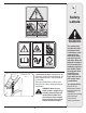
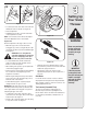
1 Safety Labels WARNING #3 Chute Clean-out Tool A chute clean-out tool is fastened to the top of the auger housing with a mounting clip. The tool is designed to clear a chute assembly of ice and snow. This item is fastened with a cable tie at the factory. Cut the cable tie before operating the snow thrower. WARNING: Never use your hands to clear a clogged chute assembly.
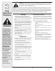
2 Safe Operation Practices WARNING This symbol points out important safety instructions which, if not followed, could endanger the personal safety and/or property of yourself and others. Read and follow all instructions in this manual before attempting to operate this machine. Failure to comply with these instructions may result in personal injury.
Operation Maintenance & Storage 1. Do not put hands or feet near rotating parts, in the auger/impeller housing or chute assembly. Contact with the rotating parts can amputate hands and feet. 2. The auger/impeller control lever is a safety device. Never bypass its operation. Doing so makes the machine unsafe and may cause personal injury. 3. The control levers must operate easily in both directions and automatically return to the disengaged position when released. 4.
3 IMPORTANT: The snow thrower is shipped with oil and WITHOUT GASOLINE. After assembly, refer to separate engine manual for proper fuel and engine oil recommendations. Loose Parts Setting Up Your Snow Thrower • The augers are secured to the auger shaft with shear pins and bow tie cotter pins. If you hit a foreign object or ice jam, the snow thrower is designed so that the pins may shear. Replacement shear pins and cotter pins are provided for your convenience. Store these safely until needed.
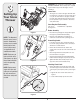
3 Setting Up Your Snow Thrower Figure 4 Figure 5 Attaching the Chute Assembly WARNING • Remove locknuts and screws securing one of the flange keepers to the chute assembly. See Figure 4. Prior to operating your snow thrower, refer to Auger Control on page 9. Read and follow all instructions carefully and perform all adjustments to verify your unit is operating safely and properly. • Loosen but do not remove the locknuts and screws on the other two flange keepers.
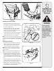
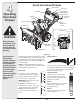
3 Setting Up Your Snow Thrower Drift Cutters (If Equipped) Drift cutters should be used when operating the snow thrower in heavy drift conditions. Alternator Lead • On models so equipped, drift cutters and hardware are assembled to the auger housing inverted. Alternator Lead • Remove the carriage bolts and wingnuts securing the drift cutters to the housing. Lamp Wire • Reposition drift cutters so they face forward as shown in Figure 9.
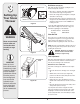
3 B A Setting Up Your Snow Thrower Auger Drive Figure 11 • Loosen the nylock nut on the drive control cable and unthread the cable one full turn. See Figure 13. • Recheck adjustment. • Retighten the nylock nut to secure the cable when correct adjustment is reached. Figure 12 NOTE: For more details, refer to Drive Control Adjustment in the Adjustment Section of this manual.
4 Operating Your Snow Thrower Know Your Snow Thrower Drive Control Shift Lever Two-Way Chute Control™ Auger Control Wheel Steering Control Headlight Gas Cap Oil Fill Chute Assembly Chute Directional Control Clean-Out Tool Engine Controls Recoil Starter Handle Electric Starter Outlet Primer WARNING Ignition Key Read, understand, and follow all instructions and warnings on the machine and in this manual before operating. Use extreme care when handling gasoline.
Auger Control The auger control is located on the left handle. Squeeze the auger control to engage the augers. Release to stop the snow throwing action. The drive control must also be released in order to stop auger. Drive Control / Auger Control Lock The drive control is located on the right handle. Squeeze the drive control to engage the wheel drive. Release to stop. This same lever also locks the auger control so you can operate the chute crank without interrupting the snow throwing process.
4 Operating Your Snow Thrower Gas & Oil Fill-Up Service the engine with gasoline and oil as instructed in the separate engine manual packed separately with your snow thrower. Read instructions carefully. Starting The Engine 1. Attach spark plug wire to spark plug. Make certain the metal loop on the end of the spark plug wire (inside the rubber boot) is fastened securely over the metal tip on the spark plug. 2. Make certain both the auger control and drive control are in the disengaged (released) position.
To Engage Drive Operating Tips 1. With the engine running near top speed, move shift lever to one of six FORWARD positions or two REVERSE positions. Select a speed appropriate for the snow conditions that exist. NOTE: Allow the engine to warm up for a few minutes. The engine will not develop full power until it reaches operating temperature. WARNING: The temperature of the muffler and the surrounding areas may exceed 150° F (65° C). Avoid these areas. 2.
5 Making Adjustments Figure 15 WARNING Read, understand, and follow all instructions and warnings on the machine and in this manual before operating. Never attempt to make any adjustments while the engine is running, except where specified in operator’s manual. Shift Rod If the full range of speeds (forward and reverse) cannot be achieved, refer to Figure 15 and adjust the shift rod as follows: 1.
5 Skid Shoes The space between the shave plate and the ground can be adjusted by raising or lowering the skid shoes. For close snow removal, as when using on a smooth concrete or asphalt driveway, place the skid shoes in the low position. Use the middle or high position when the area to be cleared is uneven. When operating on gravel, always put skid shoes in the high position. See Figure 18. Making Adjustments Adjust skid shoes as follows: 1.
6 Maintaining Your Snow Thrower Lubrication Gear (Hex) Shaft Friction Wheel IMPORTANT: Keep all grease and oil off the rubber friction wheel and drive plate. Wheels At least once a season, remove both wheels. Clean and coat the axles with a multipurpose automotive grease before reinstalling wheels. Drive Plate Auger Shaft At least once a season, remove the shear pins on auger shaft. Spray lubricant inside shaft, around the spacers. Also lubricate the flange bearings found at either end of the shaft.
Replacing Belts To remove and replace either the auger belt or the drive belt, follow the steps below and then proceed to the specific steps listed under respective sub-headings. 1. Disconnect the chute crank assembly at the discharge chute end by removing the hairpin clip and the flat washer. See Figure 19. 2. Remove the plastic belt cover, located near the engine, by removing the three self-tapping screws that secure it. See Figure 23. 3. a.
6 Maintaining Your Snow Thrower Figure 29 Figure 28 WARNING Always stop engine, disconnect spark plug, and ground against engine before cleaning, lubricating or doing any kind of maintenance on your machine. b 9. a. Using a 1/2” wrench, remove the hex screw and washer from the center of the pulley on the auger housing. See Figure 30. b. Lift the brake bracket assembly out of the pulley groove c. Remove the pulley. 10. Remove and replace auger belt inside belt keepers. Adapter 11.
Changing Friction Wheel Rubber • Drain the gasoline from the snow thrower, or place a piece of plastic under the gas cap. • Tip the snow thrower up and forward, so that it rests on the housing. • Remove screws from the frame cover underneath the snow thrower. See Figure 16. Friction Wheel Assembly Remove hex screw and washer Hex Shaft Slide hex shaft • Remove the right wheel from the axle.
7 Off-Season Storage Observe the following, when preparing your snow thrower for off-season storage: • Drain fuel into an approved container outdoors, away from any open flame. Allow engine to cool. Extinguish cigarettes, cigars, pipes and other sources of ignition prior to draining fuel. Fuel left in engine during warm weather deteriorates and will cause serious starting problems.
Problem Cause Engine fails to start 1. Choke not in ON position. 1. Move choke to ON position. 2. Spark plug wire disconnected. 2. Connect wire to spark plug. 3. Fuel tank empty or stale fuel. 3. Fill tank with clean, fresh gasoline. 4. Engine not primed. 4. Prime engine as instructed in “Operating Your Snow Thrower”. 5. Faulty spark plug. 5. Clean, adjust gap, or replace. 6. Blocked fuel line. 6. Clean fuel line. 7. Safety key not in ignition on engine. 7. Insert key fully into the switch.
9 Warranty Failure to comply with suggested maintenance and lubrication specifications will void warranty. THREE (3) YEAR LIMITED WARRANTY For three (3) years from the date of original purchase of our products, we will either repair or replace, at its option, free of charge, F.O.B. Factory or authorized service firm, any part found to be DEFECTIVE IN MATERIAL and WORKMANSHIP for the original purchaser.
NOTES: For parts and/or accessories refer to customer support on page 2. Adressez-vous au «Service après-vente» à la page 2 pour ce qui concerne les pièces et/ou accessoires.