OPERATOR’S MANUAL 3000 TRACTOR Model 3184 IMPORTANT: READ SAFETY RULES AND INSTRUCTIONS CAREFULLY Warning: This unit is equipped with an internal combustion engine and should not be used on or near any unimproved forest-covered, brush-covered or grass-covered land unless the engine’s exhaust system is equipped with a spark arrester meeting applicable local or state laws (if any). If a spark arrester is used, it should be maintained in effective working order by the operator.
TABLE OF CONTENTS PAGE TRACTOR AND DECK PREPARATION . . . . . . . . . . . . . . . . . . . . . . . . . . . 2 IMPORTANT SAFE OPERATION PRACTICES . . . . . . . . . . . . . . . . . . . . . 3 CALLING SERVICE INFORMATION . . . . . . . . . . . . . . . . . . . . . . . . . . . . . . 7 FINDING YOUR MODEL & SERIAL NUMBER . . . . . . . . . . . . . . . . . . . . . . 7 SAFETY LABELS FOUND ON YOUR UNIT . . . . . . . . . . . . . . . . . . . . . . . . 8 CONTROLS . . . . . . . . . . . . . . . . . . . . . . . . . . . . . . .
SECTION 2: IMPORTANT SAFE OPERATION PRACTICES WARNING: THIS SYMBOL POINTS OUT IMPORTANT SAFETY INSTRUCTIONS WHICH, IF NOT FOLLOWED, COULD ENDANGER THE PERSONAL SAFETY AND/OR PROPERTY OF YOURSELF AND OTHERS.READ AND FOLLOW ALL INSTRUCTIONS IN THIS MANUAL BEFORE ATTEMPTING TO OPERATE YOUR UNIT. FAILURE TO COMPLY WITH THESE INSTRUCTIONS MAY RESULT IN PERSONAL INJURY. WHEN YOU SEE THIS SYMBOL, HEED ITS WARNING.
• Never leave a running machine unattended. Always turn off blade(s), place transmission in neutral, set park brake, stop engine and remove key before dismounting. • Your mower is designed to cut normal residential grass of a height no more than 10". Do not attempt to mow through unusually tall, dry grass (e.g., pasture) or piles of dry leaves. Debris may build up on the mower deck or contact the engine exhaust presenting a potential fire hazard. • Turn off blade(s) when not mowing.
• Use extra care with grass catchers or other attachments. These can change the stability of the machine. • Before and when backing, look behind and down for small children. • Never carry children, even with the blades off. They may fall off and be seriously injured or interfere with the safe machine operation. • Keep all movement on the slopes slow and gradual. Do not make sudden changes in speed or direction.
• To reduce fire hazard, keep the machine free of grass, leaves or other debris build-up. Clean up oil or fuel spillage. Allow machine to cool at least 5 minutes before storing. • Check brake operation frequently. Adjust and service as required. • Muffler, engine and belt guards become hot during operation and can cause a burn. Allow to cool down before touching. • Before cleaning, repairing or inspecting, make certain the blade and all moving parts have stopped.
SECTION 3: CALLING SERVICE INFORMATION If you have difficulties with the unit, have any question regarding the operation or maintenance of this equipment, or desire additional information not found in this manual, contact your dealer. If you need help locating a dealer in your area, contact the Customer Dealer Referral Line by calling: 1-800-528-1009 Before calling your local dealer, make sure that you have your model and serial numbers ready.
SECTION 5: SAFETY LABELS FOUND ON YOUR UNIT IGNITION STOP WARNING AVOID SERIOUS INJURY OR DEATH STARTING INSTRUCTIONS • GO UP AND DOWN 1. BE FAMILIAR WITH CONTROLS BEFORE STARTING ENGINE AND OPERATING. 2. SET CHOKE, MOVE THROTTLE TO MID POSITION AND DEPRESS BRAKE PEDAL. 3. TURN KEY TO THE START POSITION. 4. AFTER ENGINE STARTS OPEN CHOKE. S L O P E S , N OT A C R O S S . • AVO I D S U D D E N T U R N S . • • STOPPING INSTRUCTIONS • • 1. DISENGAGE PTO AND SET PARKING BRAKE. 2.
SECTION 5: SAFETY LABELS FOUND ON YOUR UNIT SAFETY GRAPHIC - LOCATED ON TOP OF CHUTE OPENING OF DECK HANDS AND FEET SAFETY GRAPHIC – LOCATED ON DEFLECTOR CHUTE SAFETY GRAPHIC – LOCATED ON RIGHT SIDE OF DECK SAFETY GRAPHIC – LOCATED ON LEFT SIDE OF MOWER DECK Figure 2 (cont.
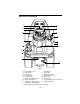
SECTION 6: CONTROLS A Q N B O M C D F E G L P (Not Shown) K J I H Figure 3 A B C D E F G H I Parking Brake Lever PTO Switch Brake Pedal Reverse Pedal Forward Pedal Center Lift Height Indicator Ignition/Light Switch Transmission Release Rod Transmission Oil Fill/Dipstick J K L M N O P Q Fuel Fill Cap Cup Holder Hydraulic Lift Lever Cruise Control Lever Choke Lever Throttle Lever Seat Adjustment Lever (Not Shown) Indicator Light Pod * Steering Wheel and Seat Removed For Clarity 10
NOTE: References to LEFT and RIGHT indicate that side of the tractor when facing forward while seated in the drivers seat. Reference to FRONT indicates the grille end of the tractor; to REAR, the drawbar end. disengage the cruise control. The brake pedal must be fully depressed to activate the safety interlock switch when starting the tractor. Reverse Pedal Steering Wheel The steering wheel is centered on the dash panel. It is used to change the direction (left or right) of the tractor while driving.
Ignition / Light Switch Fuel Fill Cap To prevent accidental starting and/or battery discharge, remove the key from the ignition switch when the tractor is not in use. The combination lights and ignition switch has four positions. See Figure 8 for a description of each position. The fuel fill cap is located on the fender to the left of the seat. Off On/Lights Cup Holder The cup holder is located on the fender to the left of the seat.
IMPORTANT: When using power Seat Adjustment Lever take-off operated equipment, best performance is achieved with the throttle lever in the “FAST” position. The seat adjustment lever is located below the seat. This lever is used to adjust the seat forward or back. Refer to Figure 12 on page 17. Indicator Light Pod A B D E C A Oil Pressure Indicator B Low Fuel Indicator C Hour Meter D Not Used E Not Used Figure 10 Hour Meter The hour meter is part of the indicator light pod in the dash panel.
SECTION 7: OPERATION Safety Interlock Switches This tractor is equipped with a safety interlock system for the protection of the operator. If the interlock system should ever malfunction, do not operate the tractor. Contact your authorized Cub Cadet Dealer. The safety interlock system prevents the engine from cranking or starting unless the brake pedal is fully depressed, and the PTO is “OFF”.
• Place the PTO switch in the “OFF” position. Place the throttle control lever between the “MID” and “FAST” positions. Then turn the ignition key to the “OFF” position. • Remove the key from the ignition switch. Driving The Tractor WARNING: Avoid sudden starts, excessive speed and sudden stops. WARNING: Do not leave the seat of the tractor without disengaging the PTO, depressing the brake pedal and engaging the parking brake.
Before operating the tractor on any slope, walk the slope to look for possible hazards such as rocks. mounds, ruts, stumps or other surface irregularities which could cause the tractor to be upset. Back the tractor with attachment up the steepest portion of each slope you intend to work. If the tractor cannot negotiate the slope in reverse, the slope is too steep to be worked. Avoid turns when driving on a slope. If a turn must be made, turn down the slope.
SECTION 8: ADJUSTMENTS B Seat Adjustment WARNING: Do not adjust the seat when the tractor is moving. Adjusting the seat while the tractor is moving could cause the operator to lose control of the tractor. To allow for the comfort of the operator, an easy to operate adjustable seat is a feature of this tractor. To adjust the seat forward or back, slide the seat adjustment lever to the left and reposition the seat to the desired location.
• Release the Parking Brake Lever. If the tractor cannot be pushed forward or rearward, the braking force must be decreased. Adjusting the Brake. Remove the rear drawbar from the frame by removing the four hex tapp screws. NOTE: The oil fill tube/dipstick will be pulled from the transmission housing. Plug or cover the hole in the transmission to prevent dirt or debris from entering.
SECTION 9: MAINTENANCE Grease front wheel bearings • Grease L/R steering knuckles • Grease front pivot axle • Check engine oil level • Change engine oil and filter ‡ Check transmission oil level • • Change transmission oil filter • Change transmission oil Check air cleaner & housing Clean & re-oil foam air pre-cleaner Change air cleaner paper cartride • • 300 Hours 250 Hours 200 Hours • • • • • • • †† † Grease deck spindles • Grease spindle belt idler arm • Grease deck caster
10 Deck Spindles Idler Arm Transmission See Maintenance Chart 10 50 10 10 20 Oil Can (High quality lubricating oil) L/R Steering Knuckles Front Pivot Axle Engine Oil: See Figure 24 on page 30 Transmission Oil- Cub Cadet Drive System Fluid Plus - ONLY Front Wheels Foot Control Pivot Points Engine Cub Cadet 251H EP Grease or equivalent No.
Accessing Engine Compartment The engine compartment can be accessed by lifting the hood upward from the recessed notches of the side panels and tipping the hood forward. If greater access is required, the tractor is equipped with quick release side panels. To remove the quick release side panels (see Figure 16): • Open the hood by pulling up. • Flip quick release fasteners up and turn to align with slots in side panels.
cables. Removing the battery from the unit is recommended. Battery Removal The battery is located under the dash panel in the frame pedestal. To remove the battery: • Open the tractor hood by lifting it at the notches in the side panels. • Remove the upper baffle of the bulkhead from the front of the dash panel by lifting upward on the locking tab on each side of the baffle. • Pull the upper end of the rubber battery strap rearward to unhook it from the tab on the pedestal.
• Left headlight — appoximately 1/4 turn counterclockwise. • Right headlight — approximately 1/4 turn clockwise. 3. Push the bulb inward and turn counterclockwise to remove from the socket. 4. Align a locking post of the bulb base with the notch in the socket, then push the bulb inward and turn clockwise to lock 5. With the terminals pointing upward, align the tab of the socket with the notch of the reflector.
For best results, fill to the “FULL” mark on the dipstick as opposed to adding a given quantity of oil. Always check the level on the dipstick before adding more oil. See Figure 18. Refer to the Lubrication Illustration for information regarding the proper type of oil to add to the transmission case. See the Specifications Chart for the quantity required. • Place the tractor on a level surface and engage the parking brake. Stop the tractor engine and remove the ignition key.
gasket contacts the filter base on the transmission housing; then tighten the filter an additional 1/2 turn. • Clean the area around the Transmission Oil Fill/Dipstick to prevent debris from entering the transmission case. • Remove the dipstick and SLOWLY pour oil into the oil fill tube. Fill the transmission case until the oil level reaches the “FULL” mark on the dipstick. • Reinstall the dipstick securely into the oil fill tube. • Start the engine and allow it to run for a few minutes.
Always use the same capacity fuse for replacement. Refer to the Specifications Chart. If the electrical system does not function, check the fuses. To replace a fuse, note the position of the fuse and pull the old fuse from the electical box. Compare the suspect fuse with Figure 21 to determine if is good or bad. GOOD BAD Figure 21 Install the new fuse in the position from which the old fuse was removed.
SECTION 10: ENGINE INFORMATION KOHLER CO. FEDERAL AND CALIFORNIA EMISSION CONTROL SYSTEMS LIMITED WARRANTY UTILITY AND LAWN AND GARDEN ENGINES The U.S. Environmental Protection Agency (EPA), the California Air Resources Board (CARB), and Kohler Co. are pleased to explain the Federal and California Emission Control Systems Warranty on your utility/lawn/garden equipment engine (herein engine).
LIMITATIONS This Emission Control System Warranty shall not cover any of the following: (a) repair or replacement required because of misuse or neglect, improper maintenance, repairs improperly performed or replacement not conforming to Kohler Co. specifications that adversely affect performance and/or durability and alterations or modifications not recommended or approved in writing by Kohler Co.
Before checking the oil level, clean the area around the oil level dipstick to prevent debris from entering the crankcase. See Figure 23. Always keep the oil level between the “FULL” and the “ADD” marks on the dipstick. See Figure 22. When checking the oil level, the engine must be cold, the dipstick must be withdrawn and wiped clean, then inserted all the way into the tube before being withdrawn for a true reading. Check the oil level only while the engine is stopped and the tractor is level.
See (Figure 24), VISCOSITY CHART, below for the proper type of oil. Above +32° F SAE 10W30 SAE 10W40 Below +32° F SAE 5W20 SAE 5W30 • Unseat the plastic dust cap from the engine oil drain valve. To prevent loss of the cap, do not remove the cap’s retaining ring from the drain valve. Remove the dipstick. • Attach the flexible tubing to the drain valve. Place an appropriate container below the open end of the tubing to collect the old oil.
To remove the spark plugs, always use a spark plug wrench. Check the gap after every 100 hours of operation. Replace a defective plug with a new plug. Set the spark plug gap at .030 inch. Tighten the plug to 18-22 ft-lbs. See your authorized dealer for the correct replacement plug. Check the air cleaner daily or before starting the engine. Check for loose or damaged components and check the condition of the filter element. Remove any buildup of dirt and debris in the air cleaner housing.
Servicing The Paper Element Inspect an replace the paper element as necessary. See Figure 26. • Loosen the air cleaner cover knob and remove the cover. • Loosen and remove the element cover wing nut. • Remove element cover by lifting straight up. • Remove the foam precleaner by sliding it up off the paper element. • Lift out the paper air filter element. • Do not wash the paper element or use pressurized air, as this will damage the element. Replace a dirty, bent or damaged element.
SECTION 11: MOWER DECK Deck Leveling Adjustments 4. The 44" mower deck is equipped with ground following front caster wheels and is designed to be operated with caster wheels on the ground. However, to ensure an even cut on all types of terrain, the mower deck should be properly leveled. The side to side leveling procedure will result in the left and right blades having corresponding cutting-edge-to ground measurements within 1/16 inch of each other.
7. Turn the hex lock nut upward (tighten) on the threads of the lift rod to raise the left side of the mower deck. Turn the lock nut down (loosen) on the threads to lower the left side of the mower deck. Outer Blades Positioned Front to Rear LH Lift Link Figure 30 3. LH Lift Rod Hex Lock Nut Figure 29 8. Recheck the measurements described in step 5. If the blade measurements are not within 1/16 inch, repeat steps 5 and 7 until the correct measurement is obtained. Refer to Figure 31.
• Loosen the hex jam nuts and lock washers on the front lift rod. 3. • From the front of the tractor, turn the front hex lock nuts clockwise to raise the front of the deck, or counterclockwise to lower the front of the deck. Remove the hex cap screws and nylon lock nuts from the rear gauge wheels and gauge wheel brackets (See Figure 33). Hex Cap Screw • Recheck the measurements described in step 3 and readjust the hex lock nuts until the proper measurements are obtained.
Removal and Installation of Mower Deck 4. Place the tractor and mower deck on a firm and level surface having enough room to accomodate the deck and tractor. WARNING: Before beginning removal, or installation of the deck, place the PTO switch in the “OFF” position, engage the parking brake lever, and turn the ignition key to “OFF” position and remove the key. Use care not to cut yourself on the sharp blades.
6. LH Lift Rod Use the hydraulic lift to fully raise the LH and RH lift links (See Figure 37). Stop the engine. LH Lift Link Notch Slot Lift Stop Bracket Release Tab VIEWED FROM RIGHT SIDE Left Lift Link Fully Raised Figure 36A Figure 37 7. Hold Down Lift Upward Figure 36B Roll the deck forward to disengage the front lift rod from the slots of the front roller bracket (See Figure 38).
Quick Latch Rod Latch Receiver Slots Front Caster Wheel Rear Gauge Wheel Upper Hole Front Lift Bracket/Rod Ass’y. Figure 39 9. From the left side of the tractor, slide the mower deck out from under the tractor. B. Installation of Mower Deck Figure 40 4. From the left side of the tractor, slide the deck under the tractor until the slots of the LH and RH rear deck brackets align approximately with the tractor lift links (See Figure 41). 5.
6. Use the tractor lift system lever to lower the lift links. 7. Unlock the left lift link by sliding the left lift rod fully rearward in the slot of the lift link (See Figure 42). spring tension will push the pins inward and, if aligned, through the hole in each implement lift link (See Figure 43). Lift Link Through Inner Hole Deck Support Pin LH Lift Rod LH Lift Link Figure 42 8. 9.
13. Slide the deck drive shaft fully onto the PTO shaft of the tractor (See Figure 45). The auto-lok collar of the drive shaft should snap into the locked position when the shaft is properly positioned on the PTO shaft. PTO Shaft Auto-Lok Collar Deck Drive Shaft grass. If necessary, remove the RH and LH belt covers by removing the six hex nuts and lock washers. The cutting blades must be kept sharp at all times.
When reinstalling the blades, be sure they are installed so that the wind wings are pointing upward toward the top of the deck. Tighten the nuts to 90 to 110 ft-lbs. (122 to 149 N·m). B. Lubrication equivalent No. 2 multipurpose lithium grease. The lube fitting for the outer spindles can be accessed by removing the button plugs in the belt covers. Use grease liberally. Excess grease will be expelled from the upper spindle seals.
2. C. Spindle Belt Replacement A worn spindle belt will affect the quality of cut from the mower deck and should be replaced. Referring to Figures 48, 50 and 52, replace the spindle belt as follows: WARNING: The idler arm and movable flat idler pulley are under spring tension. To prevent possible injury, use caution when handling the idler arm and pulley. NOTE: Clean any accumulated grass clippings from the mower deck before beginning belt replacement . Remove Spindle Belt Belt Cover 3.
6. Remove the two hex flange lock nuts and carriage bolts securing the right side of the gear box mounting bracket to the deck plate (See Figure 51). Carriage Bolts and Hex Flange Lock Nuts Gear Box Mtg. Bracket of the drive pulley, and through the center opening of the mounting bracket (See Figure 51). 2. Secure the gear box mounting bracket with the four carriage bolts and hex flange lock nuts. 3.
Mowing With Deck A. Normal Mowing WARNING: To avoid possible injury, never direct the discharge of material toward bystanders or allow anyone near the machine while in operation. Although the area has been supposedly cleared of foreign objects, small objects may be picked up and discharged by the mower. 2. Operate the tractor at full throttle and slower forward speeds. 3. Keep the blades sharp replace worn blades. 4. Follow the mowing pattern shown in Figure 53.
plug upward so that the hooks engage the deflector hinge rod (See Figure 54). 4. Push the mulching plug fully downward and lower the chute deflector. 5. To remove the mulching plug, raise the chute deflector and lift the mulching plug upward, then outward to disengage from the deck. Lower the chute deflector. Mulching Operation 1. Do not cut wet grass. For effective mulching do not cut wet grass. Wet grass sticks to the underside of the deck, preventing proper mulching and dispersal of grass clippings.
SECTION 12: TROUBLE SHOOTING Possible Cause Possible Remedy Hard To Start No fuel in fuel tank or carburetor Fill the tank with fuel. Check the fuel line, carburetor and fuel filter. Fuel ine or carburetor clogged Clean the fuel line and carburetor with a commercial carburetor cleaner. Fuel filter plugged Replace Water in fuel Drain the fuel tank and carburetor. Use new fuel and dry the sparks plugs. Choked improperly.
Possible Cause Possible Remedy Fuel tank air vent clogged Remove obstruction from the vent in the fuel tank cap. Air leakage between carburetor and engine Remove air cleaner. Tighten the carburetor and manifold mounting hardware. Replace any damaged parts as indicated in “MAINTENANCE.” Incorrect timing or faulty ignition See your authorized dealer. Brake dragging Adjust the brakes. Refer to “ADJUSTMENTS.
SECTION 14: SPECIFICATIONS Engine Manufacturer . . . . . . . . . . . . . . . . . . . . . . . . . . . . . . . . . . . . . . . . . Kohler Horsepower . . . . . . . . . . . . . . . . . . . . . . . . . . . . . . . . . . . . . . . . . . . . . 18 Cylinders . . . . . . . . . . . . . . . . . . . . . . . . . . . . . . . . . . . . . . 2 (Command) Cooling . . . . . . . . . . . . . . . . . . . . . . . . . . . . . . . . . . . . . . . . . . . . . . . . Air Fast Idle Speed . . . . . . . . . . . . . . . . . . . . . . . . .
SECTION 15: SLOPE GAUGE WARNING: Do not mow on inclines with a slope in excess of 15 degrees (a rise of approximately 2-1/2 feet every 10 feet). A riding mower could overturn and cause serious injury. If operating a walkbehind mower on such a slope, it is extremely difficult to maintain your footing and you could slip, resulting in serious injury. • Operate RIDING mowers up and down slopes, never across the face of slopes.
CUB CADET CORPORATION MANUFACTURER’S ONE YEAR LIMITED WARRANTY (COMMERCIAL USE) The limited warranty set forth below is given by CUB CADET CORPORATION (“CUB CADET”) with respect to new merchandise purchased and used in the United States, its possessions and territories.
The provisions as set forth in this Warranty provide the sole and exclusive remedy arising from the sale.
CUB CADET CORPORATION MANUFACTURER’S LIMITED WARRANTY (RESIDENTIAL USE) The limited warranty set forth below is given by CUB CADET CORPORATION (“CUB CADET”) with respect to new merchandise purchased and used in the United States, its possessions and territories.
This limited warranty does not provide coverage in the following cases: a. Routine maintenance items such as lubricants, filters, blade sharpening and tune-ups, or adjustments such as brake adjustments, clutch adjustments or deck adjustments; and normal deterioration of the exterior finish due to use or exposure. b.
SECTION 16: QUICK REFERENCE PARTS Description Part Number Engine Oil 737-3030A (10W30) 737-3049 (5W30) Air Filter CARTRIDGE FOAM PRE-CLEANER KH-47-083-03 KH-24-083-02 Engine Oil Filter KH-12-050-08 Spark Plug 759-3336 Transmission Oil Cub Cadet Drive System Fluid Plus 737-3120 - Quart 737-3121 - Gallon Transmission Oil Filter 923-3014 Mower Deck Blades 44” Mower Deck 759-3939 (3) Mower Deck Belts 44” Mower Deck 954-3098 (1) PTO Belt (set of 2) 954-3084