
User Manual

310-3000 IHT 15
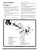
BYPASS ASSEMBLY
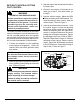
Refer to Figure 8.
DISASSEMBLY
1. Remove self tapping screw (138), and ex-
ten sion spring (136).
2. Remove snap ring (42), and bypass arm
(41).
3. Remove bypass lip seal (40).
INSPECTION
1. Inspect spring pin (137) for damage.
ASSEMBLY
1. If necessary, install new spring pin (137).
2. Install bypass lip seal (40).
3. Install bypass arm (41), and snap ring
(42).
4. Install self tapping screw (138), and ex-
ten sion spring (136).
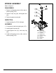
Figure 8. Bypass Assembly
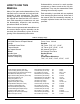
REF. Part Name
1 Main Housing
40 Lip Seal
41 Bypass Arm
42 Retaining Ring
136 Spring
137 Spring Pin
138 Screw