310-3000 Integrated Hydrostatic Transaxle Service and Repair Manual BLN-51259 Revision Dec.
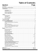
Table of Contents Section Page Foreword........................................................................................................................ i Description and Operation........................................................................................... ii Introduction.................................................................................................................. 1 General Description................................................................................
FOREWORD Headquartered in Sullivan, Illinois, Hydro-Gear® is a world leader in the design, manufacture, and service of quality hydrostatic transaxles for the lawn and garden industry. The mission of our company is to be recognized by our customers and the industry as a world-class supplier and the quality leader in everything we do. This Service and Repair Manual is designed to provide information useful in servicing the 3103000 Hydro-Gear Integrated Hydrostatic Transaxle (IHT).
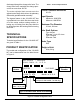
SECTION 1. DESCRIPTION AND OPERATION INTRODUCTION The purpose of this manual is to provide useful information for servicing the Hydro-Gear® 310-3000 Integrated Hydrostatic Transaxles (IHT). This manual includes transaxle general description, hydraulic schematic, technical specifications, product identification, safety, troubleshooting, maintenance, and repair procedures. The transaxle normally will not require servicing during the life of the vehicle in which it is installed.
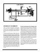
310-3000 IHT Figure 1. 310-3000 Hydraulic Flow Illustration HYDRAULIC SCHEMATIC Figure 1 provides an illustration of the hydraulic oil circuit. The oil supply for the hydraulic system of the 310-3000 IHT is also utilized for the lubrication of the planetary differential drive gears. The input shaft and pump cylinder block are turned in one direction only by the engine/drive belt/pulley combination. Output of the oil flow is controlled by the direction and amount that the swashplate is angled.
discharged through the charge relief valve. The charge relief valve maintains the charge pressure at no more than 40 PSI. The motor cylinder block mounts onto the splined motor shaft which drives the planetary differential gear/differential assembly. The bypass feature in the 310-3000 IHT has a mechanical lever which lifts the motor block off of the center section running surface, allowing any oil flowing from the pump block to be discharged into the housing without turning the motor. Table 1.
SECTION 2. SAFETY This symbol points out important safety instructions which, if not followed, could endanger the personal safety and/or property of yourself and others. Read and follow all instructions in this manual before attempting maintenance on your transaxle. When you see this symbol - HEED ITS WARNING. WARNING POTENTIAL FOR SERIOUS INJURY Inattention to proper safety, operation, or maintenance procedures could result in personal injury, or damage to the equipment.
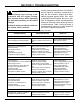
SECTION 3. TROUBLESHOOTING WARNING Do not attempt any ser vic ing or adjust ments with the engine run ning. Use extreme caution while inspecting the drive belt assembly, and all vehicle linkage! Follow all safety procedures outlined in the vehicle owner’s manual! In many cases problems with the 310-3000IHT are not related to a defective transmission or axle, but are caused by slipping drive belts, partially engaged bypass valves, and loose or damaged control linkages.
SECTION 4. SERVICE AND MAINTENANCE NOTE: Any servicing dealer attempting a warranty repair must have prior approval be fore con duct ing main tenance of a Hydro-Gear ® product unless the servicing dealer is a current Authorized Hydro-Gear Service Center. EXTERNAL MAINTENANCE Reference Table 4., Page 13 for tools required in the maintenance of the 310-3000 IHT. Regular external maintenance of the 310-3000 IHT should include the following: 1.
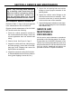
FLUIDS FLUID CHANGE The fluids used in Hydro-Gear® products have been carefully selected, and only equivalent, or better products should be substituted. This transaxle is factory filled and does not require a regular oil change. In the event of oil contamination or degradation an oil change may improve performance. Typically, an engine oil with a minimum rating of 9 cSt (55 SUS) at 230° F (110° C) and an API classification of SJ/CD is recommended.
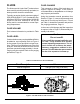
BRAKE MAINTENANCE BRAKE SETTING 1. Remove the brake arm bias spring, and then the cotter pin securing the brake castle nut. 2. Insert a 0.015" (.381 mm) feeler gage between the brake disc and top brake puck, and then set the brake by tightening or loosening the castle nut. 3. Adjust brake gap to 0.015" (.381 mm) clearance. 4. Install the cotter pin to secure the castle nut, and then install the brake arm bias spring.
RETURN TO NEUTRAL SETTING HAND CONTROL WARNING POTENTIAL FOR SERIOUS INJURY Certain procedures require the vehicle engine to be operated and the vehicle to be raised off of the ground. To prevent possible injury to the servicing technician and/or bystanders, insure the vehicle is properly secured. The return to neutral mechanism on the transmission is designed to set the directional control into a neutral position when the vehicle parking brake is engaged.
RETURN TO NEUTRAL SETTING FOOT CONTROL WARNING POTENTIAL FOR SERIOUS INJURY Certain procedures require the vehicle engine to be operated and the vehicle to be raised off of the ground. To prevent possible injury to the servicing technician and/or bystanders, insure the vehicle is properly secured. The return to neutral mechanism on the transmission is designed to set the directional control into a neutral position when the operator removes their foot from the foot control.
PURGING PROCEDURES Due to the effects air has on efficiency in hydrostatic drive applications, it is critical that it be purged from the system. These purge procedures should be implemented any time a hydrostatic system has been opened to facilitate maintenance or any additional oil has been added to the system. Air creates inefficiency because its compression and expansion rate is higher than that of the oil normally approved for use in hydrostatic drive systems.
SECTION 5. REPAIR NOTE: Any servicing dealer attempting a warranty repair must have prior approval before conducting maintenance of a Hydro-Gear® product unless the servicing dealer is a current Authorized Hydro-Gear Service Center. GENERAL INSTRUCTIONS Cleanliness is a primary means of assuring satisfactory life on repaired units. Thoroughly clean all exposed surfaces prior to any type of maintenance. Cleaning of all parts by using a solvent wash and air drying is usually adequate.
HOW TO USE THIS MANUAL Many of the parts and subassemblies of this transaxle can be removed and serviced independently of other components. The disassembly, inspection, and assembly portions of this manual are therefore laid out in subsections. Each assembly is treated as a unit, and the disassembly, inspection, and assembly procedures follow one another. Subassemblies removed to reach another component or feature need not be fully disassembled.
BRAKE ASSEMBLY (128), and washer (77). 5. Remove brake arm (124), and brake arm bias spring (141). Refer to Figures 6 and 7. DISASSEMBLY The following procedure is for model 324-3000. Reference microfiche for other models. 1. Remove lock nut (95), washer (77), brake spring (134), and washer (77) from brake pull rod (152). 6. Remove brake anti-drag compression spring (151), and two brake pins (125). 7.
INSPECTION 1. Inspect the brake pucks (120) for excessive wear. 2. Replace with new if necessary. ASSEMBLY 1. Install inner brake puck (120), and brake disc (85). 2. Assemble the brake yoke assembly, by installing puck plate (131), outer brake puck (120) into brake yoke (122). 3. Install the brake yoke assembly onto two mounting studs on housing assembly (2). Use of a feeler gage (0.015”) (.381 mm) may be helpful in retaining the brake yoke assembly at this step. 4.
BYPASS ASSEMBLY Refer to Figure 8. DISASSEMBLY 1. Remove self tapping screw (138), and extension spring (136). 2. Remove snap ring (42), and bypass arm (41). 3. Remove bypass lip seal (40). INSPECTION 1. Inspect spring pin (137) for damage. ASSEMBLY 1. If necessary, install new spring pin (137). 2. Install bypass lip seal (40). 3. Install bypass arm (41), and snap ring (42). 4. Install self tapping screw (138), and extension spring (136). REF.
CONTROL ARM ASSEMBLY Refer to Figure 9, Page 18 DISASSEMBLY NEUTRAL ASSEMBLY NOTE: The brake pull rod (152), washer (77), and cotter pin (129) must be removed before disassembling the Neutral Assembly (refer to Brake Assembly). 1. Remove bolt (88) and adjusting puck (48). 2. Remove neutral spring (46), actuating arm (35), return arm (34), and washer (87). CONTROL ARM ASSEMBLY 1. Remove upper lock nut (95), washer (77), spring (93), spacer (94), washer (77), and friction puck (37). 2.
REF. 26 31 32 33 34 35 36 37 46 48 Part Name Control Arm Trunnion Arm Trunnion Bushing Trunnion Arm Lip Seal Return Arm Actuating Arm Stud Friction Puck Spring Adjusting Puck REF.
TORQUE BRACKET ASSEMBLY Refer to Figure 10. DISASSEMBLY 1. Remove lock nut (142), and bolt (143), from torque bracket (102). 2. Remove torque bracket (102), from main housing (1). ASSEMBLY 1. Install torque bracket (102), onto main housing (1). 2. Install lock nut (142), and bolt (143), to secure torque bracket (102) to main housing (1). Reference Table 5, Page 13 for torque values. 18 REF. 1 102 142 143 Part Name Main Housing Torque Bracket Lock Nut Bolt Figure 10.
FAN AND PULLEY ASSEMBLY Refer to Figure 11. DISASSEMBLY 1. Remove jam nut (115) from input shaft (12). 2. Remove fan/pulley assembly (104), (103), (107). INSPECTION 1. Inspect fan (104) for broken and/or damaged blades. If necessary to replace fan (104), remove screws (107), and fan (104), from pulley (103). ASSEMBLY 1. Install fan/pulley assembly (104), (103), (107) onto input shaft (12). 2. Secure fan/pulley assembly (104), (103), (107) onto shaft (12) by installing jam nut (115), per table 5, Page 13.
INPUT SHAFT ASSEMBLY Refer to Figure 12. DISASSEMBLY 1. Drain the oil from the transaxle. 2. Remove snap ring (7), input shaft lip seal (5), and spacer (4). 3. Remove input shaft assembly (12), (8), (6). REF. 1 4 5 6 7 8 12 13 Part Name Main Housing Spacer Lip Seal Wire Retaining Ring Snap Ring Ball Bearing Input Shaft Block Thrust Washer 4. Remove washer (13) from cavity. INSPECTION 1.
CHARGE PUMP ASSEMBLY Refer to Figure 13. DISASSEMBLY Note: Before disassembling, note the orientation of the charge pump cover (54). Scribe or mark the charge pump cover (54) for correct orientation during assembly. 1. Remove two screws (29) from the charge pump cover (54), and remove charge pump cover (54). 2. Remove o-ring (53) and gerotor assembly (52). INSPECTION 1. Inspect gerotor assembly (52), cavity of charge pump cover (54), plate on which cover is mounted for damage or excessive wear. REF.
LOWER HOUSING/FILTER/ MANIFOLD ASSEMBLY Refer to Figure 14. NOTE: Charge Pump assembly must be removed before the following steps can be performed. DISASSEMBLY 1. Remove the eleven housing screws (50) and lower cover (51), and remove sealant. 2. Remove screw O-rings (157). 3. Remove spring (145) and ball (146). 4. Remove filter (55) and charge manifold (56). 5. Remove O-ring (144). INSPECTION 1. Inspect filter (55) and manifold (56), replace if necessary. 2. Inspect O-ring (144) and screw O-rings (157).
PLANETARY DIFFERENTIAL ASSEMBLY 2. Remove all sealant from both housings and inspect seal lands for damage when cleaning. Refer to Figure 15, next page. 3. If miter gear (65) needs replaced, remove jam nut (73) from axle shaft (76). NOTE: Brake Assembly, and optional Return to Neutral have to be removed before the following steps can be performed. ASSEMBLY 1. Remove the axle hub assembly (118) on control side by removing nuts (119), and hub assemblies (118). 1. If necessary, install L.H.
D B C A REF. 1 2 58 59 60 61 62 63 64 65 66 67 68 Part Name Main Housing R.H. Housing Assembly Carrier Pin REF. Part Name Planetary Gears 70 Washer 67t Spur Gear 71 Washer 21t Sun Gear 63 51t Ring Gear Planetary Thrust Plate 64 Planetary Carrier 51t Ring Gear 65 Differential Miter Gear Planetary Carrier 66 Differential Miter Gear Differential Miter Gear 73 Hex Jam Nut Differential Miter Gear 76 Axle Shaft Differential Shaft 80 Torx Head Screws Differential Thrust Plate 96 Bearing Sleeve C A REF.
MOTOR/CENTER SECTION/ PUMP ASSEMBLY Refer to Figures 16 and 17, (next pages). NOTE: Brake Assembly, Input Assembly, Charge Pump Assembly, and Low er Housing/Filter/Manifold Assembly have to be removed before the following steps can be performed. (25) for excessive wear (grooving or smearing). 2. Inspect each piston (23), spring (18), and piston seat (22) in the motor cylinder block assembly. 3. Inspect seal lands of the 21cc motor cylinder block assembly (21) for excessive wear (grooving or smearing). 1.
NOTE: To hold bypass plate (38) in position, apply a small drop of grease to its slot before installing. 13. Again using the assembly tool to compress pistons (22), slide thrust bearing (25), behind the tool, into its cavity in front of the cylinder block (21) and assembled pistons. 8. Install spacer (27), 16T pinion gear (28), washer (82), snap ring (83), and washer (82) onto motor shaft (24). NOTE: The thick race of thrust bearing (25) must face the pistons. 14.
REF. 1 3 13 14 15 16 17 18 19 Part Name Main Housing Center Section Assembly Block Insert Washer Block Spring 10cc Cylinder Block Pistons Springs Piston Washers Block Spring REF. 20 21 22 23 24 25 27 28 Part Name Bushing 21cc Cylinder Block Pistons Springs Motor Shaft Thrust Bearing Spacer 16t Pinnion Gear REF. Part Name 38 43 44 53 57 82 83 144 Bypass Plate Pin Screws O-Ring Bearing Retainer Washer Retaining Ring O-ring Figure 17.
DIRECTIONAL CONTROL ASSEMBLY Refer to Figure 18. NOTE: The Motor/Center Section/Pump Assembly must be disassembled before this procedure can be completed. DISASSEMBLY 1. Remove swashplate assembly (10). Disassemble swashplate assembly by removing thrust bearing (11) from swashplate (10). The thick race of thrust bearing must face pistons. REF. 1 9 10 11 30 Part Name Main Housing Cradle Bearing Variable Swashplate Thrust Bearing Slot Guide 2. Remove slot guide (30). INSPECTION Figure 18.
TRANSAXLE INSTALLATION Use the following procedure to complete installation of the transaxle on the vehicle. 1. Install and secure the transaxle on the vehicle according to instructions in the vehicle owner’s manual. 2. Install the hub assembly (118, Figure 13) on the shaft. Install hex nut (119, Figure 13).
Figure 19.
ITEMS LIST Part numbers are not provided in this manual. See Service Schematic or Distributor for part numbers. NO. 1 2 3 4 5 6 7 8 9 10 11 12 13 14 15 21 24 25 26 27 28 29 30 31 32 33 34 35 36 37 38 39 40 41 42 43 44 46 48 50 51 52 53 54 55 56 57 58 59 60 61 62 63 64 65 66 67 68 69 70 71 73 74 75 76 77 DESCRIPTION Main Housing Assembly R.H.
SECTION 6. GLOSSARY OF TERMS Axial Piston: Type of design for hydraulic motors and pumps in which the pistons are arranged parallel with the spindle (input or output shaft). Bantam Duty: A descriptive term relating to the product capacity (meaning: light duty). Bypass Valve: A valve whose primary function is to open a path for the fluid to bypass the motor or pump. Also referred to occasionally as the freewheel valve or dump valve.
Hydrostatic Transaxle: A multicomponent assembly including a gear case and a hydrostatic transmission. Hydrostatic Transmission: The combination of a hydraulic pump and motor in one housing to form a device for the control and transference of power. Inlet Line: A supply line to the pump. Integrated Hydrostatic Transaxle (IHT): The combination of a hydrostatic transmission and gear case in one housing to form a complete transaxle. Manifold: A conductor which provides multiple connection ports.
NOTES 34 310-3000 IHT
NOTES 310-3000 IHT 35
© 2008 HYDRO-GEAR Rev. P2 Printed in U.S.A.