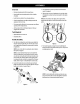
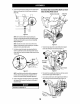
A0 1A Overview 3. Place shift lever In Forward-6 position or fastest forward B . speed (If equipped). Remove packaging materials from snow blower, 4. Observe lower rear area of equipment to be sure both cables + Rotate handle into the upright position, Refer to Handle {it equipped) are aligned and seated properly in roller guides Assembly. {Figure 2). + Install the chute. Refer to Chute Assembly Options.
6. Attach the two carnage obits (b} and nuts {a} removed in Step 2. Finish securing the handle by tightening the top two nuts loosened in Step 2, See Figure 4. fetter ta Figure 5 helot 1o identify your “Chute Control Style” and continua ta the “Assembly” instructions for your specific style on pages 8-13.
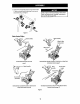
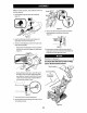
b5 Overhead Chute Rotation Control 3. Finish securing chute control head o chute support bracket with wing aut {2} and hex screw {b) removed in Step 1 (Figure 9). Chute Control Rod 4, Insert chute contra rod into the support bracket on rear of the dash panel (Figure 10). LA Figure 6 1. Remove wing nut (2) and hex screw (b} from chute control head and dives pin and bow-tel cotter pin {d) from chute support bracket.
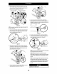
ASSEMBLY Overhead Chute Rotation Control w/ 2-Way Pitch or 4-Way Pitch & Rotation Control Chute Control fold 2 Way/d Way Control Figure 12 1. Remove hairpin clip (a), wing nut (b} and hex screw from chute control head and dives pin {d) and bow-tie carter pin {e} from chute support racket [Figure 13). t Chute Control Head 11O Figure 13 NOTE: For smoothest operation, cables should all be to the left of the chute concrete rod. 2.
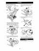
VA TR 6. Insert chute control rod into pinion gear under handle panel, #ake sure to line up hale In rod with arrow on pinion gear {Figure 18), Figure 18 NOTE: Chute control rod will fit snug into pinion gear.
ASSEMBLE NOTE:For smoothest operation, cables should all be to the deft of the chute contra rod. 4. Remove hairpin clip from rear of chute control head (Figure 23}, Figure 23 . Insert flex shaft (b} into rear of church control bead, with hairpin slip removed in Step 4 (Figure 23} . Perform one of the following to connect the flex shaft to the chute control rod coupling: Medals with Overhead Rotational Insert hex end of flex shaft into chute control rod coupling under handle pane (Figure 24).
AR 1. Remove hairpin clip wing nut {b) and hex screw from chute control head. Remove dives pin (d) and bow-tie cotter pin {e} from chute support bracket (Figure 29). Chute Control Head Chute Support Bracket 5. insert other end of chute control rod into couplet below handle panel. Make sure to line up flat end of rod and flat end of couplet. You may zed to rotate rod around until these two surfaces line up (Figure 33 Inset).
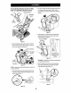
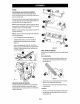
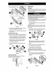
Sat-Up CHUTE CONTROL CABLE ROUTING (iF EQUIPPED) For models equipped with 2-way or 4-way chute controls, electric chute control and/or chute-pitch controls, ensure control cables are rated properly. Chute control cables are routed through 2 single wire guide {a) on top of the engine and/or through two wire guides (b) located on the front and left side of the engine {Figure 35).
LR A Adjustments SKID SHOES Snow blower skid shoes are adjusted at a factory setting roughly /8" below the shave plate, Adjust them upward or downward, if desired, prior to operating. Tool-less Adjustable Drift Cutter A WARNING Use extreme caution when aerating on or near gravel and adjust skid shoes to dear gravel or crushed rock surfaces to Tao-less Nonacid picking up and throwing objects which could cause Adjustable Drift Cutter serious injury or property damage.