
Use and Care Manual

9Section 2 — ASSembly & Set-Up
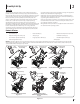
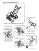
Overhead Chute Control (with Chute Control Rod)
Figure 2-14
1. Remove wing nut (a) and hex
screw (b) from chute control head and
clevis pin (c) and cotter pin (d) from
chute support bracket. Position chute
assembly (forward-facing) over chute
base. See Figure 2-15.
(a)
(b)
(c)
(d)
Chute
Control Head
Chute
Chute
Support
Bracket
Chute
Base
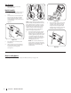
Figure 2-15
2. Place chute assembly onto chute base
and secure chute control head to chute
support bracket with clevis pin (c) and
cotter pin (d) removed in Step 1. See
Figure 2-16.
(c)
(d)
Figure 2-16
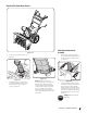
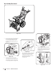
3. Finish securing chute control head to
chute support bracket with wing
nut (a) and hex screw (b) removed in
Step 1. See Figure 2-17.
(a)
(b)
Figure 2-17
4. Insert chute control rod into the support
bracket on rear of the dash panel. See
Figure 2-18.
Figure 2-18
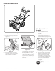
5. Remove hairpin clip (a) from rear of
chute control head. See Figure 2-19.
6. Insert chute control rod (b) into rear
of chute control head. See Figure 2-19.
Secure chute control rod to chute
control assembly with hairpin clip (a)
removed in Step 5.
(a)
(b)
Figure 2-19
STOP
STOP! Continue to Set-Up
(page 14).