
Use and Care Manual


22 Section 4— Service
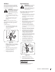
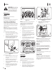
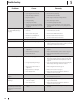
Chute Control Rod
(Two Way & Four Way Chute
Control) (If Equipped)
To adjust chute control rod for increased
engagement into the handle panel control,
proceed as follows:
1. Remove hairpin clip (a) from hole closest
to chute assembly on chute rotation
assembly.
2. Pull out chute control rod until hole in
it lines up with second hole in chute
rotation assembly. See Figure 4-12.
(a)
Figure 4-12
3. Reinsert hairpin clip (a) through this hole
and chute control rod.
Chute Assembly
Refer to Assembly & Set-up section (page
15) for instructions on adjusting chute
assembly.
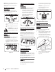
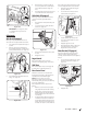
Chute Assembly (Overhead Chute
Control) (If Equipped)
If chute fails to remain stationary during
operation, pre-load of chute can be adjusted
by tightening hex nut found on front of chute
control assembly.
1. To increase preload, tighten
hex nut (a) clockwise in ¼ turn intervals.
The chute control rod will need to be
held stationary when tightening the nut.
See Figure 4-13.
(a)
Figure 4-13
2. If chute directional control is difficult to
crank, decrease preload by loosening
hex nut counter-clockwise in ¼ turn
intervals.
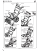
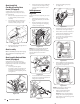
Belt Replacement
Auger Belt
To remove and replace auger belt, proceed as
follows:
1. Allow engine to run until it is out of
fuel. Do not attempt to pour fuel from
engine.
2. Remove plastic belt cover on front of
engine by removing two self-tapping
screws (a). See Figure 4-14.
(a)
(a)
Figure 4-14
NOTE: On models equipped with the LED
headlight on top of the auger housing,
make sure to unplug the wire harness before
removing the belt cover as shown in
Figure 4-15.
Figure 4-15
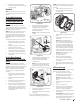
3. Loosen and remove two bolts (a) and flat
washers (b) securing belt guide. Remove
belt guide. See Figure 4-16.
(a)
(a)
(b)
(b)
Figure 4-16
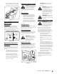
4. Roll auger belt off engine pulley.
See Figure 4-17.
Figure 4-17
5. Carefully pivot the unit up and forward
so that it rests on the auger housing.
6. Remove frame cover from underside of
unit by removing self-tapping screws
which secure it. See Figure 4-4.
7. Loosen and remove shoulder bolt (a)
which acts as a belt keeper.
See Figure 4-18.
NOTE: Multi-speed unit shown.
(a)
Figure 4-18
8. Remove belt from around auger pulley,
and slip it between support bracket and
auger pulley. See Figure 4-19.
Figure 4-19
NOTE: Engaging auger control will ease
removal and reinstallation of belt.
9. Replace auger belt by following
instructions in reverse order.
NOTE: Make sure to reinstall shoulder
bolt (a) and reconnect spring to frame
after installing a replacement auger belt.
Refer to Figure 4-18.
(b)