Hydrostatic Zero-Turn Residential Riding Mower Turf Equipment MODEL 23HP Z-Force 60 OPERATOR’S AND SERVICE MANUAL
TABLE OF CONTENTS Foreword. . . . . . . . . . . . . . . . . . . . . . . . . . . . . . . . . . . . . . . . . . . . . . . . . . . . . . . . . . . . . . . 3 General Safety Operations . . . . . . . . . . . . . . . . . . . . . . . . . . . . . . . . . . . . . . . . . . . . . . . . . 4 A.General Operation. . . . . . . . . . . . . . . . . . . . . . . . . . . . . . . . . . . . . . . . . . . . . . . . . . 4 B. Slope Operation . . . . . . . . . . . . . . . . . . . . . . . . . . . . . . . . . . . . . . . . . . . . . .
FOREWORD The Hydrostatic Zero-Turn Riding Mower provides superb maneuverability and mid-mount cutting. The machine incorporates many safety features that should be studied by all operators before use. The list of safety precautions should receive particular attention. This manual presents all of the operating and maintenance instructions necessary to keep your mower at peak efficiency. If operated and maintained properly, your mower will give dependable service.
WARNING • • • The engine exhaust, some of its constituents, and certain vehicle components contain or emit chemicals known to the State of California to cause cancer, birth defects or other reproductive harm. This unit is equipped with an internal combustion engine and should not be used on or near any unimproved forest-covered, brush-covered, or grass-covered land unless the engine’s exhaust system is equipped with a spark arrester meeting applicable local or state laws (if any).
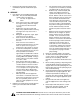
17. 18. 19. 20. 21. 22. should not be driven up or down a ramp onto a trailer or truck under power, because the unit could tip over causing serious personal injury. The unit must be pushed manually on a ramp to load or unload properly. Never make a cutting height adjustment while the engine is running if the operator must dismount to do so. Wear sturdy, rough-soled work shoes and closefitting slacks and shirts. Do not wear loose fitting clothes or jewelry. They can be caught in moving parts.
7. Remove the key when the machine is left unattended to prevent unauthorized operation. a. D. SERVICE 1. 2. Use extreme care in handling gasoline and other fuels. They are extremely flammable and the vapors are explosive. a. Use only an approved container. b. Never remove fuel cap or add fuel with the engine running. Allow the engine to cool at least two minutes before refueling. c.
9. 10. 11. 12. 13. 14. 15. 16. After striking a foreign object, stop the engine, remove the wire from the spark plug and thoroughly inspect the mower for any damage. Repair the damage before restarting and operating the machine. Grass catcher components are subject to wear, damage and deterioration, which could expose moving parts or allow objects to be thrown. For your safety protection, frequently check the components and replace with manufacturers recommended parts when necessary.
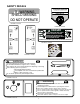
SAFETY DECALS TO REDUCE THE RISK OF INJURY, D O N OT O P E RAT E M OW E R U NL E S S DISCHARGE CHUTE COVERORGRASS C A T C H E R IS I N I T S P R O P E R P L A C E . WARNING SHIELD MISSING DO NOT OPERATE D AN GER K E E P H A N D S a n d FE E T A W A Y Part Number: 00030635 Part Number: 01002166 DANGER KEEP HANDS AND FEET AWAY. DO NOT OPERATE MOWER UNLESS CHUTE DEFLECTOR OR ENTIRE GRASS CATCHER IS IN ITS PROPER PLACE. S30503 ASSEMBLE CHUTE DEFLECTOR TO THIS UNIT BEFORE OPERATING.
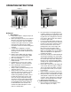
SPECIFICATIONS GENERAL INFO. Controls: Parking Brake: Seat: Frame: Instrumentation: Front Caster Wheels: Drive Wheels: Tire Pressure: Fuel Tank: Ground Speed: Net Weight: Engine ignition and start switch; throttle; choke; left and right steering levers; electric blade clutch switch; parking brake; mower deck lift Internal, mechanical linkage attached to the brake handle Adjustable seat with armrests.
OPERATING INSTRUCTIONS Figure. 1 Electric Blade Clutch Switch Figure. 2 Tach and Hour Meter Engine throttle Choke Lever Ignition Switch A.General k. Be careful when crossing gravel paths or roadways. Always turn off the blade clutch switch and wait until the blades stop rotating and raise the cutting deck to the transport position. Always allow other vehicles to have the right of way. l.
B.Controls b. Avoid turning downhill if possible, if not use extra care and go slowly. c. Avoid turning when going downhill, traction is at a minimum going downhill. d. Do not operate with discharge side of the mower toward streets, buildings, playgrounds, parking lots, other machines, animals, and other people. e. Avoid operation or use extreme care if the traction surface is wet, unstable, or slippery. f.
Steering Levers Deck Lift Handle Brake Figure. 4 Fuel Shutoff Valve Figure. 3 4. Electric Blade Clutch Switch: (See Figure 1.) Located on the right side of the mower beside the ignition switch. This is an “on/off” push pull switch that controls the electric blade clutch which supplies power to the cutting blades through the PTO.
C.Initial Adjustments 1. Check the fluid levels and tires: Note: These checks should be made daily, before starting the engine. b. a. Fuel: Using a good grade of unleaded, regular gasoline (for a gasoline engine), fill the fuel tank (beside the engine on the left or right side of the mower). When the fuel reaches one inch from the top of the tank, stop. DO NOT OVERFILL. Space must be left for expansion. b. Engine Oil: (Filled at the factory before shipment.
desired cutting height has been attained. If the dimensions are not correct, repeat steps “c.” through “f.” above. 4. That no non-approved devices are installed. 5. That all safety signs and decals are properly installed and legible. e. This is a one person machine, operator only! Riders are not permitted under any circumstance! f. To start the engine on the machine: 1.
the same side that was retarded — I.E., to turn counter-clockwise (to the LEFT), move the LEFT lap bar rearward more than the right side, and to turn clockwise (to the RIGHT), move the RIGHT lap bar rearward more than the left side. NOTE: If one lap bar is in the neutral position and the other is retarded, the turn side tire will not rotate and a “pivot turn” will be executed. Turf defacement could occur (if on grass) as well as potential damages to the traction surface and the tire.
i. Gasoline Engine: Once the engine starts, push the choke on halfway and as the engine warms, push the choke off all the way. 5. 4. Operating the Mower: Operating a zero-turning-radius mower is not like operating a tractor-type riding mower. The zero-turning-radius mower is much more maneuverable and much less fatiguing to operate. However, getting used to the fingertip control of the zeroturning-radius mower takes some practice.
Linch Pins Linch Pins Figure. 6 Height of Cut Clevis Pin MAINTENANCE AND SERVICE h. To install reverse the process. 2. Changing a Blade: a. Jack up the front of the mowing deck about one foot and block it in that position. b. Wrap a rag around one end of the blade and grasp it to prevent it from turning, or secure the blade by placing a block of wood between the blade and the deck housing. c. Use a 1-1/8" socket wrench on the pulley side of the spindle to secure. d.
Hydraulic Tank Cover Plate Spindle Hydro Release Levers Transmission Figure. 8 Figure. 7 f. Note: Blades that cannot be easily bal- Using a wrench or socket rachet remove four hex nuts, and the four hex head cap screws. Remove the spindle assembly. anced—REPLACE. 3. Changing the Blade Drive Belts: a. Set the parking brake. Remove ignition key and both spark plug caps. b. Unscrew the wing nuts from the deck covers and remove both covers. c.
c. Remove the mower deck. See Mower Deck on page 17. d. Raise the seat forward to expose the hydraulic oil fill point. e. Clean the area around the hydraulic fill oil cap. f. Remove hydraulic fill oil cap. g. Place a suitable container (at least 2 gallon) under the hydraulic reservoir and the transaxels. h. Remove the hydraulic filter from each transaxle to allow hydraulic oil to drain. (See Figure 8) i. Coat new filter seals with oil before installation. j.
and try to start the engine. The engine should not start. If it does, the left steering lever switch must be repositioned or perhaps replaced. Open the left steering lever to the neutral position and swing the right steering lever up to the operating position and try to start the engine. The engine should not start. If it does, the right steering lever switch must be repositioned or perhaps replaced. If the engine does not start, Open the right steering lever to the neutral position and start the engine.
Then tighten the locknut on the end of the axle assembly. the seat switch, the blade clutch switch and the electric blade clutch. Then check out the seat switch, the blade clutch switch and finally the electric blade clutch. Lower the mower off the jack and continue mowing. The wheel with the leaking tire should be taken to the maintenance area, the tire inflated to 20 psi and the wheel placed in a large bucket of water.
Note: If you wish to move the mower by pushing, you must release the dynamic braking. Locate the levers at the rear of the mower. Pull both levers out and lock in position. After pushing the mower to the desired location, return both levers to the operating position (See page 18 Figure 8). Note: Always wipe off the hydraulic tank fill cap and the area around it before removing the cap to prevent dirt from contaminating the oil.
rear. To make the adjustment, place the steering levers in the opened-out neutral position and set the parking brake, shutoff the engine, take the key from the ignition switch and pivot the seat forward. If the mower creeps to the right, you will adjust the linkage on the left side of the mower and vice-versa. Remove the cap screw and lock washer that secure the linkage control arm rod end bearing to the control lever pivot. Loosen the jam nut which prevents the rod end bearing from turning.
MAINTENANCE SCHEDULE 7. D. Every 100 Hour Checks A. Daily Checks 1. 1. Before starting engine: a. Check the fuel level. b. Check the engine oil level. c. Check the hydraulic oil level. d. Check the hydraulic hoses for leaks, abrasion, kinks, twists, or a flattened condition. e. Check the tires and tire pressure. Drive Tires: 8-10 psi. Front Caster Wheels: 20-25 psi. f. Check the spindle belt, the mower drive belt and the hydro drive belt. g. Check the blades.
OIL CHART Apply a few drops of SAE 15W40 oil or use a spray lubricant. Apply the oil to both sides of pivot points. Wipe off any excess. Start engine and operate mower briefly to insure that oil spreads evenly.
Performance Adjustments B. Enginge RPM Check and Adjustment Description High RPM Spec. Low RPM Spec. 23 HP Kohler 3750 +/-75 1650 +/-100 23 HP Kawasaki 3750 +/-75 1650 +/-100 A. High Speed Tracking Adjustment If mower tracks to one side with both lap bars in fully forward position: 1. 2. 3. 4. 5. Check air pressure in all four tires: a. Pressure should be within specified ranges and balanced side-to-side. b. Rear tires 8-10 psi. recommended (20 psi MAX.) c. Front tires 20-25 psi.
C. Deck Corner Ball Wheel Roller Settings 4. 1. Matching the set heights of the ball rollers on the four corners of the mower deck to the desired cut height will prevent edge scalping and minimize any side-to-side variance in cut height. 2. There are three height adjustment holes in the bracket that mount the ball rollers to the deck. a. Use the top set of holes for cut heights of 2 inches or lower. b. c.
F. Deck leveling Procedure 1. 2. 3. 4. 5. 6. 7. to-ground height at the rear of the blade tip should be 1/8" to 1/4” higher than the front tip. This is referred to as blade pitch. The sam height difference should be true for the left blade, measured front and back. 8. To adjust the blade pitch the deck pitch must be adjusted. Loosen the inner jam nuts at the rear of the horizontal threaded rods. Start at Point C to raise the rear of the deck, tighten the rear outer jam nut to raise the deck pitch.
WIRING DIAGRAM GD: 02000167 29
SLOPE GAUGE TTE A1 5 ° S LOP E OR A FENCE POST A CORNER OF A BUILDING A POWER POLE SIGHT AND HOLD THIS LEVEL WITH A VERTICAL TREE USE THIS PAGE AS A GUIDE TO DETERMINE SLOPES WHERE YOU MAY NOT OPERATE SAFELY. FO L D O N DO D LI N E , REP RE S E NTIN G 15° WARNING Do not mow on inclines with a slope in excess of 15 degrees (a rise of approximately 2-1/2 feet every 10 feet). A riding mower could overturn and cause serious injury.
MANUFACTURER’S LIMITED WARRANTY FOR: TWO-YEAR RESIDENTIAL ONE-YEAR COMMERCIAL Proper maintenance of your Cub Cadet equipment is the owner’s responsibility. Follow the instructions in your operator’s manual for correct lubricants and maintenance schedule. Your Cub Cadet dealer carries a complete line of quality lubricants and filters for your equipment’s engine, transmission, chassis and attachments.