Hydrostatic Zero-Turn Residential Riding Mower Turf Equipment MODEL 20HP Z-Force 44 23HP Z-Force 50 OPERATOR’S AND SERVICE MANUAL
TABLE OF CONTENTS Foreword. . . . . . . . . . . . . . . . . . . . . . . . . . . . . . . . . . . . . . . . . . . . . . . . . . . . . . . . . . . . . . . 3 General Safety Operations . . . . . . . . . . . . . . . . . . . . . . . . . . . . . . . . . . . . . . . . . . . . . . . . . 4 A. General Operation . . . . . . . . . . . . . . . . . . . . . . . . . . . . . . . . . . . . . . . . . . . . . . . . . 4 B. Slope Operation . . . . . . . . . . . . . . . . . . . . . . . . . . . . . . . . . . . . . . . . . . . . . .
FORWARD The Hydrostatic Zero-Turn Riding Mower provides superb maneuverability and mid-mount cutting. The machine incorporates many safety features that should be studied by all operators before use. The list of safety precautions should receive particular attention. This manual presents all of the operating and maintenance instructions necessary to keep your mower at peak efficiency. If operated and maintained properly, your mower will give dependable service.
WARNING • • • The engine exhaust, some of its constituents, and certain vehicle components contain or emit chemicals known to the State of California to cause cancer, birth defects or other reproductive harm. This unit is equipped with an internal combustion engine and should not be used on or near any unimproved forest-covered, brush-covered, or grass-covered land unless the engine’s exhaust system is equipped with a spark arrester meeting applicable local or state laws (if any).
17. 18. 19. 20. 21. 22. should not be driven up or down a ramp onto a trailer or truck under power, because the unit could tip over causing serious personal injury. The unit must be pushed manually on a ramp to load or unload properly. Never make a cutting height adjustment while the engine is running if the operator must dismount to do so. Wear sturdy, rough-soled work shoes and closefitting slacks and shirts. Do not wear loose fitting clothes or jewelry. They can be caught in moving parts.
7. Remove the key when the machine is left unattended to prevent unauthorized operation. 9. D. SERVICE 1. 2. 3. 4. 5. 6. 7. 8. Use extreme care in handling gasoline and other fuels. They are extremely flammable and the vapors are explosive. a. Use only an approved container. b. Never remove fuel cap or add fuel with the engine running. Allow the engine to cool at least two minutes before refueling. c.
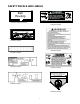
SAFETY DECALS AND LABELS DANGER Belt Routing KEEP HANDS AND FEET AWAY. DO NOT OPERATE MOWER UNLESS CHUTE DEFLECTOR OR ENTIRE GRASS CATCHER IS IN ITS PROPER PLACE. S30503 ASSEMBLE CHUTE DEFLECTOR TO THIS UNIT BEFORE OPERATING. Part Number: 777I22421 (for 44” Deck) LOWERCUTTING DECKHIGHER Part Number: 777S30503 To unlock, pull part of handle inward. Lift unlocked handle to increase cutting height. To lock, release upper part of handle to move outward.
SPECIFICATIONS Engine: Type: Air Cleaner: Lube System: Starter: Traction Drive: Cutter Deck;Drive: Clutch: Deck Lift: Cutting Height: No.
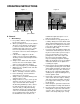
OPERATING INSTRUCTIONS Figure. 1 Hour Meter Figure. 2 Choke Electric Blade Clutch Switch Engine throttle Ignition Switch A. General maintain the uphill side lap bar “essentially” in a fixed position. k. Be careful when crossing gravel paths or roadways. Always turn off the blade clutch switch and wait until the blades stop rotating and raise the cutting deck to the transport position. Always allow other vehicles to have the right of way. l.
2. Safety Awareness when Mowing a. Do not operate on steep slopes, those above 15 degrees (27% slope). b. Avoid turning downhill if possible, use extra care and go slowly. c. Avoid turning when going downhill, traction is at a minimum going downhill. d. Do not operate with discharge side of the mower toward streets, buildings, playgrounds, parking lots, other machines, animals, and other people. e. Avoid operation or use extreme care if the traction surface is wet, unstable, or slippery. f.
Steering Levers Brake Figure. 4 Figure. 3 Deck Lift Handle Fuel Shutoff Valve 8. Seat Adjustment Lever: The Seat Adjustment Lever is located beneath the seat. The Seat Adjustment Lever is used to move the seat forward and backward. To place the seat in the desired position pull the seat adjustment lever to the left then push the seat forward or back to the desired position. Release the lever so the seat will lock in place. 9.
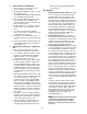
C. Initial Adjustments 1. Check the fluid levels and tires: b. Note: These checks should be made daily, before starting the engine. a. Fuel: Using a good grade of unleaded, regular gasoline, fill the fuel tank (beside the engine on the left side of the mower). When the fuel reaches one inch from the top of the tank, stop. DO NOT OVERFILL. Space must be left for expansion. b. Engine Oil: (Filled at the factory before shipment.) Pull out the oil dipstick, wipe it off and reinsert it.
have been attained. If the dimensions are not correct, repeat steps “c.” through “f.” above. 4. That no non-approved devices are installed. 5. That all safety signs and decals are properly installed and legible. e. This is a one person machine, operator only! Riders are not permitted under any circumstance! f. To start the engine on the machine: 1.
(toward center of machine). Slowly, move both lap bars toward the front of the machine until the machine begins to move forward — release the lap bars and the machine should stop. The more that the lap bars are moved toward the front of the machine, the faster the machine will move in the forward direction. Release the lap bars and the machine should stop traveling forward. (This is a safety check, the normal procedure is for the operator to slowly bring the lap bars to the neutral position). 4.
h. Gasoline Engine: Once the engine starts, move the choke/throttle to the detent as the engine warms. b. Use the Deck Lift Handle to raise the mowing deck to the transport position. c. Drive the mower to the cleanup or storage area. d. Move the throttle to slow. e. Place the steering levers in the neutral position. f. Set the parking brake. g. Turn off the ignition switch and take the key from the switch. h. Close the fuel shutoff valves. 4.
Linch Pins Figure. 6 “J” Pin Note: There is a certain amount of spring allow the underside of the cutting deck to thoroughly rinse. j. Move the PTO control to the “OFF” position. k. Turn the engine off. l. Turn the water off, and detach the hose coupler from the water port on your mower deck. m. Clean up the grass clippings and other materials washed from underneath the mower deck, and dispose of them properly. tension due to the weight of the deck.
WARNING: Never mow with dull blades! Blades that are bent should be replaced! The cutting blades are sharp and can cause severe injury. Wrap the cutting surface of the blade with a rag to avoid injury. 3. Sharpening the Blade: a. Set the parking brake. b. Clean any debris from the blades. Keep blades sharp and free of build up at all times. c. Sharpen blades evenly at the original 30° angle to maintain balanced cutting blades. Do not sharpen the underside of the blades.
c. Hydrostatic Transaxles Figure 9 Store the battery with a full charge. A discharged battery will freeze (refer to the table below). Specific Gravity Freezing Temp (°F) 1.265 -71 1.250 -62 1.200 -16 1.150 5 1.100 16 d. Recharge battery when ever the specific gravity value is less than 1.225 4. Installing the Battery D.Electrical Circuit Note: The battery is delivered from the fac- Danger: tory fully charged and filled with electrolyte. Read General Safety Precautions Nos. 9 and 10. 1.
must be off, the parking brake must be engaged, and both steering levers must be opened-out to the side in the neutral position. Once the engine is started, the seat must be occupied and the parking brake must be released before either of the steering levers is folded up to the operating position or the engine’s electronic ignition will be grounded out and the engine will stop. Also, the seat must be occupied before the blade clutch switch can cause the blades to rotate. 8.
stop when you dismount from the operator’s seat, the seat switch must be replaced. e. Electric PTO Clutch: This clutch operates when the engine is running, the operator is in the operator’s seat and the blade clutch switch is turned on. This electric clutch is a fairly trouble free device.
system locks the traction wheels. 2. Note: To move the mower forward or in reverse by pushing, you must release the dynamic braking. Locate the release levers at the rear of the machine. Pull them toward the rear and lower the wide area of the rod into the keyhole slot. (See photo below). If the mower creeps, first determine whether it creeps to the right or left side and which direction the mower moves — to the front or the rear.
B. Every 25 Hour Checks deposits from forming. Replace the fuel filter. g. Gasoline Engine Only: Remove the spark plugs and pour approximately one ounce of oil into each cylinder. Crank the engine one or two turns to spread the oil evenly on the cylinder walls. Replace the spark plugs. h. Clean the battery and make sure it is fully charged. i. Jack the mower up and store it on blocks to take the weight off of the tires. 2. To Put the Mower Back in Service: a. Check the battery. Charge if necessary. b.
. OIL CHART Apply a few drops of SAE 20W-50 engine oil, grease, or use a spray lubricant. Apply the oil to both sides of pivot points. Wipe off any excess. Start engine and operate mower briefly to insure that oil spreads evenly.
Performance Adjustments B. Engine RPM Check and Adjustment Table 1 A. High Speed Tracking Adjustment If mower tracks to one side with both lap bars in fully forward position: Check air pressure in all four tires: a. Pressure should be within specified ranges and balanced side-to-side. b. Rear tires 8-10 psi recommended (20 psi MAX.) c. Front tires 20-25 psi recommended (28 psi MAX. 2.
g. Verify proper throttle adjustment by checking RPM readings as outlined above. b. Remove the bolts and lap bar and reposition to the second set of holes in the mounting block. c. Replace the bolts and nuts, and tighten to 28-34 ft-lbs. 1. If angular adjustments are also required, nuts can be tightened until snug at this point. d. The same adjustments should be made to both sides of the mower. 6. To adjust the front-to-rear angle of the lap bars, a.
3. Check the right and left rear Drive tire pressure. Adjust as necessary to 8-10 psi. 4. Measure blade-to-ground height at the front tip of the right blade. To obtain an accurate measure, align blades in parallel with mower centerline, (i.e. front to back). 5. Measure blade-to-ground height at the front tip of the left blade. Be sure to measure at the blade tip with the blades arranged in proper position. 6.
WIRING DIAGRAM GD: 02000461 27
USE THIS PAGE AS A GUIDE TO DETERMINE SLOPES WHERE YOU MAY NOT OPERATE SAFELY. SIGHT AND HOLD THIS LEVEL WITH A VERTICAL TREE A POWER POLE A CORNER OF A BUILDING OR A FENCE POST DO N DO TTE D LI NE, REP RES ENT ING A 15° S LOP E 28 SLOPE GAUGE FOL 15° WARNING Do not mow on inclines with a slope in excess of 15 degrees (a rise of approximately 2-1/2 feet every 10 feet). A riding mower could overturn and cause serious injury.
MAINTENANCE RECORD DATE WORK PERFORMED DATE 29 WORK PERFORMED
MAINTENANCE RECORD DATE WORK PERFORMED DATE 30 WORK PERFORMED
MAINTENANCE RECORD DATE WORK PERFORMED DATE 31 WORK PERFORMED
MANUFACTURER’S LIMITED WARRANTY FOR: TWO-YEAR RESIDENTIAL ONE-YEAR COMMERCIAL Proper maintenance of your Cub Cadet equipment is the owner’s responsibility. Follow the instructions in your operator’s manual for correct lubricants and maintenance schedule. Your Cub Cadet dealer carries a complete line of quality lubricants and filters for your equipment’s engine, transmission, chassis and attachments.