OPERATOR’S MANUAL 2000 TRACTOR Model Number 2176 IMPORTANT: READ SAFETY RULES AND INSTRUCTIONS CAREFULLY Warning: This unit is equipped with an internal combustion engine and should not be used on or near any unimproved forestcovered, brush-covered or grass-covered land unless the engine’s exhaust system is equipped with a spark arrester meeting applicable local or state laws (if any). If a spark arrester is used, it should be maintained in effective working order by the operator.
KOHLER CO. FEDERAL AND CALIFORNIA EMISSION CONTROL SYSTEMS LIMITED WARRANTY UTILITY AND LAWN AND GARDEN ENGINES The U.S. Environmental Protection Agency (EPA), the California Air Resources Board (CARB), and Kohler Co. are pleased to explain the Federal and California Emission Control Systems Warranty on your utility/lawn/garden equipment engine (herein engine). For California, engines produced in 1995 and later must be designed, built and equipped to meet the state’s stringent anti-smog standards.
CONTENTS Section I II III IV V VI Emission Control Systems Warranty ... Tractor and Deck Preparation.............. Safe Operation Practices ..................... Product Graphics ................................. To The Owner ...................................... Serial No. Location .............................. Controls and Indicators ........................ Operation ............................................. Adjustments ......................................... Maintenance .......................
WARNING • The engine exhaust, some of its constituents, and certain vehicle components contain or emit chemicals known to the State of California to cause cancer, birth defects or other reproductive harm. • This unit is equipped with an internal combustion engine and should not be used on or near any unimproved forest-covered, brush-covered, or grass-covered land unless the engine’s exhaust system is equipped with a spark arrester meeting applicable local or state laws (if any).
13. Mow only in daylight or good artificial light. DO: 14. Do not operate the machine while under the influence of alcohol or drugs. Mow up and down slopes, not across. 15. Watch for traffic when operating near or crossing roadways. Watch for holes, ruts or bumps. Uneven terrain could overturn the machine. Tall grass can hide obstacles. 16. Use extra care when loading or unloading the machine into a trailer or truck.
5. Never allow children under 14 years old to operate the machine. Children 14 years and over should only operate the machine under close parental supervision and proper instruction. 8. After striking a foreign object, stop the engine, remove the wire from the spark plug and thoroughly inspect the mower for any damage. Repair the damage before restarting and operating the mower. 6.
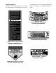
PRODUCT GRAPHICS Keep product safety graphics (decals) clean. Replace any safety graphic that is damaged, destroyed, miss- ing, painted over or can no longer be read. Replacement safety graphics are available through your dealer. STARTING INSTRUCTIONS 1. BE FAMILIAR WITH CONTROLS BEFORE STARTING ENGINE AND OPERATING. 2. SET CHOKE, MOVE THROTTLE TO MID POSITION AND DEPRESS BRAKE PEDAL. 3. TURN KEY TO THE START POSITION. 4. AFTER ENGINE STARTS OPEN CHOKE. STOPPING INSTRUCTIONS 1.
TO THE OWNER Cub Cadet tractor Model 2176 is equipped with a 42inch mower deck and shipped with a mulching kit. The information in this manual has been prepared in detail to help you better understand the correct operation and maintenance of this equipment. Before you operate the tractor, study this manual carefully. Additional copies may be ordered from your dealer at a nominal price authorized dealer periodically or at least once a year, depending on its hours of use.
SECTION I. CONTROLS AND INDICATORS Your Cub Cadet Tractor has been safety engineered. This section gives a brief description of the function and location of the various controls and indicators. A Thoroughly acquaint yourself with all the controls and indicators before attempting to start or operate the tractor. B I C J F D K E H G L O M N A. B. C. D. E. F. G. H.
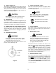
A. LOW OIL INDICATOR This indicator will illuminate when the engine oil level is low. If this indicator illuminates, stop the tractor immediately and check the engine oil level. If the oil level is within the operating range, but the light remains on, contact your Cub Cadet dealer. E. THROTTLE CONTROL LEVER This lever controls the speed of the engine. When set in a given position, the control cable will maintain a uniform engine speed.
I. BRAKE PEDAL The brake pedal is located at the front of the right running board above the forward control pedal. Press down to stop the tractor and disengage the cruise control. The brake pedal must be fully depressed to activate the safety interlock switch when starting the tractor. J. FORWARD CONTROL PEDAL The forward control pedal is located at the front of the right running board below the brake pedal. Slowly press down on the pedal to start moving forward.
Q. SAFETY INTERLOCK SWITCHES This tractor is equipped with a safety interlock system for the protection of the operator. If the interlock system should ever malfunction, do not operate the tractor. Contact your authorized Cub Cadet Dealer. The safety interlock system prevents the engine from cranking or starting unless the brake pedal is fully depressed, and the PTO switch is in the “OFF” position.
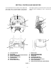
UPPER FRONT WING NUT GRASP REAR WING NUT SIDE PANEL REAR TAB ON PANEL RETAINER WITH TAPERED GUIDE GRILLE GROOVE IN DASH PANEL GRASP Figure 8 13
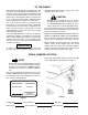
SECTION II. OPERATION Gasohol (up to 10% ethyl alcohol, 90% unleaded gasoline by volume) is an approved fuel. Other gasoline/alcohol blends are not approved. WARNING Methyl Tertiary Butyl Ether (MTBE) and unleaded gasoline blends (up to a maximum of 15% MTBE by volume) are approved fuels. Other gasoline/ ether blends are not approved. RECEIVE INSTRUCTION - Read the operator’s manual. Learn to operate this machine SAFELY. Don’t risk INJURY or DEATH. 1.
• The safety interlock system will automatically shut off the engine if the operator leaves the seat before engaging the brake pedal lock. TRACTOR BREAK-IN PROCEDURE CAUTION • The safety interlock system will automatically disengage the PTO if the reverse control pedal is pressed down with the PTO in the “RUN” position. To re-engage the PTO, release the reverse control pedal, move the PTO switch into the “OFF” position and then engage the PTO while seated.
5. Turn the ingnition key to the “START” position and hold until the engine starts; however, do not crank the engine continuously for more than 10 seconds at a time. Once the engine starts, gradually adjust the choke as needed to keep the engine running until warmed up, then push the choke control all the way in. CAUTION Do not use the forward or reverse control pedals to change the direction of travel when the tractor is in motion.
DRIVING ON SLOPES 1. Start and run the engine a few minutes to warm up. Refer to the SLOPE GAUGE on page 57 to help determine slopes where you may not operate safely. 2. With the mowing deck, snow thrower, etc. installed and the engine running at approximately 50% throttle, engage and disengage the clutch at ten second intervals (ten seconds ON-ten seconds OFF) five times. The engine choke may have to be pulled out slightly to accomplish this.
SECTION III. ADJUSTMENTS This section contains adjustment information for the Model 2176 tractor. Adjustment information for the 42inch deck is located in Section V – Mower Deck beginning on page 33. ADJUSTING THE SEAT WARNING Do not adjust the seat when the tractor is moving. Adjusting the seat while the tractor is moving could cause the operator to lose control of the tractor. 2. Release the brake pedal lock. If the tractor cannot be pushed forward or rearward, the braking force must be decreased.
WHEEL ALIGNMENT The front wheels should toe-in approximately 1/8 to 1/4 inch, as measured across dimensions A and B shown in Figure 12. PERPENDICULAR TO FRAME 5. Disconnect the front ball joints from the steering arms by removing the hex lock nuts (Refer to Figure 13). Manually move each wheel to achieve the required toe-in and equal D measurements. 6. Loosen the jam nuts from the ball joints (See Figure 13). LOWER STEERING ARM BALL JOINT JAM NUT TIE ROD HEX LOCK NUT STEERING ARM Figure 13 Figure 12.
2. Pivot the ends of the axle up and down to check for binding. If the axle is binding, loosen the lock nuts (See Figure 14) until binding is eliminated. WARNING Place the tractor on a firm and level surface and chock the front wheels before raising the rear wheels from the ground. Use jack stands to support the rear of the tractor when raised. PIVOT AXLE ADJUSTMENT BOLTS LOCK NUT 2. Raise the rear of the tractor, so that the rear tires are at least one inch above the surface, and set it on jack stands.
3 2 4 1. 2. 3. 4. 5. 6. 7. 8. 9. 10. Front Control Rod Rear Control Rod Hex Tap Screw Pivot Sleeve Neutral Arm Control Arm Hex Cap Screw Centering Spacer Neutral Bracket Hairpin Cotter (Not Shown) 5 1 10 5 6 CONTROL CAM 7 8 9 Figure 15.
CARBURETOR ADJUSTMENTS WARNING When making adjustments to the carburetor while the engine is running, disengage the PTO clutch and engage the brake pedal lock. Keep clear of all moving parts and be careful of all hot surfaces. 2. Idle Speed Setting: Place the throttle control into the “idle” or “slow” position. Set the low idle speed to 1200 rpm (± 75 rpm) by turning the low idle speed adjusting screw in or out. Check the speed using a tachometer (See Figure 17).
SECTION IV. MAINTENANCE ENGINE MAINTENANCE • Maintenance, repair, or replacement of the emission control devices and systems, which are being done at the customer’s expense, may be performed by any engine repair establishment or individual. Warranty repairs must be performed by an authorized Kohler service outlet. Never operate the engine with the oil level below the “L” mark or above the “F” mark on the dipstick. NOTE Check the oil level only while the engine is stopped and the tractor is level.
ADDING OIL WARNING CAUTION If the tractor has recently been operated, the engine and surrounding areas may be hot. Use caution not to burn yourself when removing the side panels, draining the oil from the crankcase, and changing the oil filter. Never overfill the engine crankcase. The engine may overheat and/or damage may result if the crankcase is below the “LOW” mark or over the “FULL” mark on the dipstick.
While the engine oil is warm, proceed as follows: FILLING THE CRANKCASE NOTE CAUTION A 12 inch length of flexible tubing is supplied in the owner’s manual package and should be used to drain the engine oil. 1. Place the tractor on a level surface and engage the brake pedal lock. Stop the tractor engine and remove the ignition key. 2. Clean around the base of the oil filter, oil level dipstick, dipstick tube, and the oil filler cap to prevent debris from entering the crankcase. 3.
CHECKING TRANSMISSION OIL LEVEL NOTE Check the oil level only while the engine is stopped and the tractor is level. Check the oil level of the transmission case before each use to see that it is filled to the correct level. Before checking the transmission oil level, clean the area around the oil fill plug/dipstick to prevent debris from entering the transmission case. Always keep the oil level between the “FULL” and the “ADD” marks on the dipstick (See Figure 20).
2. Clean the area around the transmission drain plug to prevent debris from entering the transmission case. Remove the drain plug and allow the transmission oil to drain into a clean container having a capacity of more than 6 quarts. Reinstall the drain plug (Refer to Figure 21). CAUTION If the transmission oil is to be re-used, cover the container holding the drained oil to prevent contamination. Contaminated transmission oil can damage the hydro transmission. TRANSMISSION OIL FILTER Figure 22 7.
1. Unfasten the air cleaner cover retaining knob and remove the air cleaner cover (See Figure 23). 2. Remove the foam precleaner by sliding it up off the paper element (See Figure 23). 3. Remove the wing nut and element cover plate, then lift out the paper air filter element. 1 3 2 4 5 5. When servicing the air cleaner, check the air cleaner base. Make sure it is secured and not bent or damaged. Also check the element cover for damage or improper fit. Replace all damaged air cleaner components.
HEADLIGHTS SPARK PLUG Refer to SPECIFICATIONS when replacement of head lamp bulbs is necessary. WARNING To avoid possible injury, be sure the engine is off and has cooled before making any adjustments or repairs. WARNING Allow the engine and surrounding surfaces to cool before changing the head lamp bulbs. NOTE Replace headlight bulbs as follows: (See Figure 25) 1. Unplug the wire harness leads from the headlight socket terminals. Note which wire connects to each terminal before disconnecting.
FUSES Always use the same capacity fuse for replacement. Refer to SPECIFICATIONS. If the electrical system does not function, check the fuses. To replace a fuse, pull the old fuse from the fuse holder and install the new fuse. GENERAL BATTERY INFORMATION WARNING a. Battery posts, terminals and related accessories contain lead and lead compounds. Wash Hands after handling. b. Battery acid must be handled with great care, as contact with it can burn and blister the skin.
BATTERY REMOVAL OR INSTALLATION 5. Lift the battery upward and remove from the left side of the tractor. WARNING Battery posts, terminals and related accessories contain lead and lead compounds. Wash Hands after handling. HOLDDOWN STRAP When removing the battery, disconnect the battery cables in the following order to avoid arcing and the resulting sparks: Battery Removal: 1. Disconnect the Negative cable. 2. Disconnect the Positive cable. Battery Installation: 1. Connect the Positive cable. 2.
TIRES MOUNTING TIRES ON THE RIM Keep the pneumatic tires properly inflated. Overinflation will cause operator discomfort. Under-inflation will cause short tire life. WARNING Do not mount a tire unless you have the proper equipment. Do not inflate the tire above the recommended pressure. Do not stand over the tire assembly when inflating. Accidental over inflation could cause an explosive separation of the tire and rim, which could result in serious injury of death.
SECTION V. MOWER DECK This section contains adjustment, removal, installation, and maintenance information for the 42-inch mower deck. Instructions for installation and removal of the optional mulching plug are located at the end of this section. SIDE-TO-SIDE LEVELING ADJUSTMENT A. DECK LEVELING ADJUSTMENTS 3. The mower deck front and rear gauge wheels should be installed in their uppermost position in the deck brackets to prevent contact with the hard, level surface below.
2 4 3 1 9. Loosen the upper jam nut on the hanger bracket and turn away from the adjustment ferrule. Turn the lower lock nut upward (tighten) on the threads of the hanger bracket to raise the right side of the mower deck. Turn the lock nut down (loosen) on the threads to lower the right side of the mower deck (Refer to Figure 30). 10. Raise the lift handle to the highest position and recheck the blade measurements described in step 6.
3. Initially adjust the front lift rod to allow 5/8 inch of thread to protrude beyond both lock nuts of the front lift rod/bracket assembly (Refer to Figure 32). NOTE The front lift rod must be against the back of both slots in the deck front roller bracket. If one side of the rod is not against the back of the slot after attaining the correct front pitch to the deck, tighten the front lock nut on that side until the rod just contacts the back of the slot. FRONT LIFT ROD BRACKET LOCK NUT 5/8" 9.
clearance between the wheel and level surface. Secure with the lock nut. NOTE e. Note the position of the index hole used; then install the other rear gauge wheel and the front ball wheels into the corresponding index hole of the other guage wheel brackets. Gauge wheels are intended to prevent scalping of the lawn, and are not meant to be used to set the cutting height. Do not run the deck on the guage wheels. To adjust the height of the gauge wheels, place the tractor on a firm and level surface.
B. REMOVAL AND INSTALLATION OF DECK ASSEMBLY PTO BELT REMOVAL OF DECK MOWER DECK CENTER DOUBLE PULLEY WARNING Before removing the mower deck, place PTO switch in the “OFF” position, engage brake pedal lock, turn the ignition key to “OFF” position and remove the key from switch. Disconnect the spark plug wire additional safety. the the the the for 1. Position the tractor and mower deck on a firm, level surface.
WARNING The exhaust system is HOT. To avoid personal injury, allow the engine and exhaust system to cool before proceeding with the following PTO belt removal instructions. 7. Raise the tractor implement lift handle to its highest setting, Slide the mower deck forward, so the front lift rod rests to the rear of, and free of, the front roller bracket slots of the deck (Refer to Figure 41). FRONT LIFT ROD 4.
INSTALLATION OF DECK TRACTOR LATCH RECEIVER (BOTH SIDES) WARNING Before performing the mower deck installation, place the PTO switch in the “OFF” position, engage the brake pedal lock, turn the ignition key to the “OFF” position and remove the key from the switch. Disconnect the spark plug wire for additional safety. QUICK ATTACH ROD FRONT LIFT ROD/BRACKET ASSEMBLY WARNING SHOULDER BOLT (BOTH SIDES) When handling the mower deck, be careful not to cut yourself on the sharp blades. 1.
3. Make sure the slot in both rear deck brackets aligns with the implement lift links on each side of the tractor (Refer to Figure 46). SLOT IN REAR DECK BRACKETS (BOTH SIDES) QUICK ATTACH ROD FRONT LIFT ROD/ BRACKET ASSEMBLY IMPLEMENT LIFT LINKS (BOTH SIDES) Figure 48 Figure 46 4. Refer to Figure 47 to ensure the correct orientation of the front lift rod/bracket assembly [form (bend) in sides of rod point downward]. From the front of the tractor, push downward and hold the tractor quick-attach rod.
NOTE REAR DECK BRACKET SLOTS It may be necessary to lift each side of the deck and maneuver it slightly to align the support pins with the holes of the lift links. Make certain the support pins are fully extended through the lift links to prevent the mower deck from disengaging the lift links while mowing. DECK WARNING The deck idler arm lever is spring loaded. Release it slowly. DECK SUPPORT PIN DISENGAGED Figure 50 7.
15. Connect the spark plug wire. MOWER DECK CENTER DOUBLE PULLEY PTO BELT PTO CLUTCH PULLEY PTO BELT Figure 53 FRONT OF DECK 11. Twist the PTO belt 1/4 turn to engage the narrow sides of the belt into the grooves of the two tractor front-lower pulleys (Refer to Figure 54). Figure 55 LEVER STOP BRACKET TRACTOR FRONT LOWER PULLEYS IDLER ARM LEVER PTO BELT FRONT LIFT ROD/BRACKET ASSEMBLY Figure 56 Figure 54 12.
After replacing the blades, apply grease the exposed threads at the bottom of the spindle bolts to prevent rust buildup. WARNING When servicing the mower deck, be careful not to cut yourself on the sharpened blades. Clean the underside of the mower deck at the end of the mowing season or when buildup of cut material on the underside is noticed. Also remove the belt covers and remove any accumulated grass clippings. If using the mulching option, clean the underside of the deck frequently.
SPINDLE DRIVE BELT REPLACEMENT D. INSTALLATION OF MULCHING PLUG In order to replace the spindle drive belt, refer to Figures 58 and 59 and proceed as follows: WARNING 1. Remove the hardware that secures the spindle belt covers to the deck. Before installing the mulching plug, place the PTO switch in the “OFF” position, engage the brake pedal lock, turn the ignition key to the “OFF” position and remove the key from the switch to avoid accidental starting and injury. 2.
SECTION VI. OFF-SEASON STORAGE If the machine is to be inoperative for a period longer than 30 days, the following procedures are recommended: WARNING Drain fuel into an approved container outdoors, away from open flame. a. Drain any large volume of fuel from the tank by disconnecting the fuel line from the in-line fuel filter near the engine. b.
SECTION VII. MOWING MOWING WARNING To avoid possible injury, do not allow anyone in the area opposite the discharge chute while mowing. Although the area has been supposedly cleared of foreign objects, small objects may be picked up and discharged by the mower. WARNING Never direct the discharge of material toward bystanders or allow anyone near the machine while in operation. For best results it is recommended that the first two laps should be cut with the discharge thrown towards the center.
OPTIONAL EQUIPMENT AND ACCESSORIES When you purchased your tractor, you probably had it completely equipped for your particular needs at the time. However, later you may wish to obtain optional equipment or accessories. These items and other allied equipment can be purchased from, and installed by, your authorized Cub Cadet dealer.
MAINTENANCE CHART Operation to be performed Before each use Clean grille, engine air inlet screen, dash intake screen and side panel screens X Fill fuel tank X Check transmission oil level Replace transmission oil filter 50 hours or twice a season After first 5 hours 100 hours or yearly X After first 10 hours X X Check battery terminals and case X Grease front axle pivot bolt X Grease steering knuckles X After first 50 hours X Every 100 hours thereafter X After first 10 hours X Clean cool
TROUBLE SHOOTING Possible Cause Possible Remedy HARD TO START No gasoline in fuel tank or carburetor ..................... Fill the tank with gasoline. Check the fuel line, carburetor and fuel filter. Fuel line or carburetor clogged................................ Clean the fuel line and carburetor with a commercial carburetor cleaner. Fuel filter plugged.................................................... Replace. Water in gasoline.....................................................
TROUBLE SHOOTING Possible Cause Possible Remedy LACK OF POWER Air cleaner clogged ................................................. Service the air cleaner element. Refer to “MAINTENANCE.” Engine overload ...................................................... Reduce the load. Engine overheated.................................................. Make sure the air intake screen, shrouding, engine fins, side panels, dash intake screen and grille are free of accumulated dirt and debris.
LUBRICATION TABLE Check at Hours Change at Hours Capacity Engine crankcase Check before each use 100 Approx. 4 pints Hydro transmission and transaxle with filter Check before each use Add as needed Approx. 6 qts Point of Lubrication Anticipated Air Temperature Above + 32°F Below + 32°F Cub Cadet Engine Oil SAE 10W30 or 10W40 Cub Cadet Engine Oil SAE 5W20 or 5W30 Cub Cadet Drive System Fluid Plus NOTE: Cub Cadet Drive System Fluid Plus is specially formulated for this application.
LUBRICATION GUIDE WARNING The service life and reliability of any machine depends upon the care it is given. Proper lubrication is a very important part of that care. This lubrication schedule reflects the minimal requirements to maintain the equipment. More frequent inspections and maintenance is preferable. NOTE: We do not recommend the use of a pressure washer or garden hose to clean your unit. They may cause damage to electrical components; spindles; pulleys; bearings; or the engine.
LUBRICATION GUIDE —Before Each Use 1. Engine filler cap and Check the oil (with the engine stopped) and add sufficient new oil to bring it to dipstick the “FULL” mark on the dipstick. Do not overfill. Do not operate the engine if the oil level is below the “LOW” mark on the dipstick. 2. Transmission oil level and fill port Check the oil with the engine stopped. Keep the lubricant up to the “FULL” mark on the dipstick. NOTE: The transmission oil level and fill port services the following: 1. Rear axle 2.
CHECK OIL — 2 LEVEL BEFORE EACH USE 10 — 6 50 — 12 10 — 8 10 — 7 10 — 6 10 — 6 10 — 4 50 — 11 100 — 14 50 — 13 50 — 12 10 — 5 30 — 10 1— BOTH SIDES 30 — 9 BOTH SIDES 10 — 3 LEFT SIDE 100 — 15 CHECK OIL LEVEL BEFORE EACH USE LUBRICATION GUIDE
SPECIFICATIONS 2176 CAPACITIES Fuel Tank ........................................................................ Crankcase (approximately) ............................................. Transmission Case (approximately) ................................ HYDROSTATIC DRIVE Speed: Forward................................................................ Reverse ................................................................ ENGINE Make and Model ..............................................................
ON D O LINE , RE PRE SEN TIN WARNING 15° TTE D GA 15° SLO PE Do not mow on inclines with a slope in excess of 15 degrees (a rise of approximately 2-1/2 feet every 10 feet). A riding mower could overturn and cause serious injury. If operating a walk-behind mower on such a slope, it is extremely difficult to maintain your footing and you could slip, resulting in serious injury. Operate RIDING mowers up and down slopes, never across the face of slopes.
CUB CADET CORPORATION MANUFACTURER’S ONE YEAR LIMITED WARRANTY (COMMERCIAL USE) The limited warranty set forth below is given by CUB CADET CORPORATION (“CUB CADET”) with respect to new merchandise purchased and used in the United States, its possessions and territories. c.
CUB CADET CORPORATION MANUFACTURER’S LIMITED WARRANTY (RESIDENTIAL USE) The limited warranty set forth below is given by CUB CADET CORPORATION (“CUB CADET”) with respect to new merchandise purchased and used in the United States, its possessions and territories.
MAINTENANCE PARTS CHART MODEL 2176 SERIES 2000 17 HP KOHLER ENGINE OIL Engine Oil Requirements approx. . . 4 pints Part No. Cub Cadet engine oil Ambient temperature viscosity (Grade SG or SH) Above +32°F SAE 10W30 or 10W40 Below +32°F SAE 5W20 or 5W30 737-3030A (10W30) 737-3049 (5W30) Air Filter Requirements AIR FILTER CARTRIDGE Part No. Clean air filter per instructions in your Operator’s Manual . . . . under Maintenance - Air cleaner.