@ OPERATOR'S MANUAL 2000 TRACTOR Model Number 2186 IMPORTANT: READ SAFETY RULES AND INSTRUCTIONS CAREFULLY Warning: This unit is equipped with an internal combustion engine and should not be used on or near any unimproved forestcovered, brush-covered or grass-covered land unless the engine's exhaust system is equipped with a spark arrester meeting applicable local or state laws (if any). If a spark arrester is used, it should be maintained in effective working order by the operator.
FEDERAL KOHLER CO. AND CALIFORNIA EMISSION CONTROL SYSTEMS LIMITED WARRANTY UTILITY AND LAWN AND GARDEN ENGINES The U.S. Environmental Protection Agency (EPA), the California Air Resources Board (CARB), and Kohfar Co. are pleased to explain the Federal and California Emission Control Systems Warranty on your uti_itygawn/garden equipment engine (herein engine). For California, engines produced in 1995 and later must be designed, built and equipped to meet the state's stringent anti-smog standards.
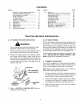
CONTENTS Section I II Ill IV V Vl Section 2 3 4 7 8 8 9 14 18 23 33 45 VII Emission Control Systems Warranty ... Tractor and Deck Preparation .............. Safe Operation Practices ..................... Product Graphics ................................. To The Owner .................................... Serial No. Location ............................. Controls and Indicators ........................ Operation ............................................. Adjustments ...................................
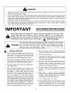
WARNING • The engine exhaust from this product contains chemicals known to the State of California to cause cancer, birth defects or other reproductive harm. • This unit is equipped with an internal combustion engine and should not be used on or near any unimproved forest-covered, brush-covered, or grass-covered land unless the engine's exhaust system is equipped with a spark arrester meeting applicable local or state laws (if any).
13. Mowonlyin daylightor goodartificiallight. 14. Do not operatethe machinewhile underthe influenceofalcoholor drugs. 15.Watchfortrafficwhenoperatingnearor crossing roadways. 16. Useextra care whenloadingor unloadingthe machineintoatraileror truck.Thisunitshouldnot bedrivenupordowna rampontoa trailerortruck underpower,becausethe unit could tip over causingseriouspersonalinjury.Theunitmustbe pushedmanuallyon a rampto loador unload properly. 17.
5. Never allow childrenunder 14 years old to operatethe machine.Children14yearsandover shouldonly operatethe machineunderclose parentalsupervisionandproperinstruction. 6. 7. ,_ Use extra care when approaching blind corners, shrubs, trees or other objects that may obscure your vision of a child or other hazard. Remove the key when the machine is left unattended to prevent unauthorized operation. IV. SERVICE 1. 9.
PRODUCT GRAPHICS ing, painted over or can no longer be read. Replacement safety graphics are available through your dealer. Keep product safety graphics (decals) clean.
TO THE OWNER Cub Cadet tractor Model 2186 is equipped with a 44inch mower deck, and includes a mulching plug. The information in this manual has been prepared in detail to help you better understand the correct operation and maintenance of this equipment. Before you operate the tractor, study this manual carefully. Additional copies may be ordered from your dealer at a nominal price authorized dealer periodically or at least once a year, depending on its hours of use.
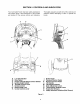
SECTION I. CONTROLS AND INDICATORS Your Cub Cadet Tractor has been safety engineered. This section gives a brief description of the function and location of the various controls and indicators. A Thoroughly acquaint yourself with all the controls and indicators before attempting to start or operate the tractor. B F K H L O \ ',>/ A. B, C. D. E. F. G. H.
A. LOW OIL INDICATOR E. THROTTLE This indicator will illuminate when the engine oil level is low. If this indicator illuminates, stop the tractor immediately and check the engine oil level. If the oil level is within the operating range, but the light remains on, contact your Cub Cadet dealer. This lever controls the speed of the engine. When set in a given position, the control cable will maintain a uniform engine speed.
I. BRAKE PEDAL The brake pedal is located at the front of the right running board above the forward control pedal. Press down to stop the tractor and disengage the cruise control. The brake pedal must be fully depressed to activate the safety interlock switch when starting the tractor. J. \i/ FORWARD CONTROL PEDAL The forward control pedal is located at the front of the right running board below the brake pedal. Slowly press down on the pedal to start moving forward.
Q. SAFETY INTERLOCK SWITCHES This tractor is equipped with a safety interlock system for the protection of the operator. If the interlock system should ever malfunction, do not operate the tractor. Contact your authorized Cub Cadet Dealer. The safety interlock system prevents the engine from cranking or starting unless the brake pedal is fully depressed, and the PTO switch is in the "OFF" position.
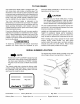
UPPER FRONT WING NUT j," REAR WIN( SIDE PANEL" RETAINER WITH TAPERED GUIDE GRILLE GROOVEIN DASH PANEL GRASP Figure 8 13
SECTION II. OPERATION Gasohol (up to 10% ethyl alcohol, 90% unleaded gasoline by volume) is an approved fuel. Other gasoline/alcohol blends are not approved. WARNING RECEIVE INSTRUCTION operator's manual. machine SAFELY. DEATH. 1. Read Learn to operate this Don't risk INJURY or Before starting the engine or beginning operation, be familiar with the controls. The operator must be seated, the PTO switch in the "OFF" position and the brake pedal fully depressed. 2. Keep all shields in place.
• The safety interlock system will automatically shut off the engine if the operator leaves the seat before engaging the brake pedal lock. • The safety interlock system will automatically disengage the PTO if the reverse control pedal is pressed down with the PTO in the "RUN" position. To re-engage the PTO, release the reverse control pedal, move the PTO switch into the "OFF" position and then engage the PTO while seated.
5, Turn the ingnition key to the "START" position and hold until the engine starts; however, do not crank the engine continuously for more than 10 seconds at a time. Once the engine starts, gradually adjust the choke as needed to keep the engine running until warmed up, then push the choke control all the way in. I CAUTION Do not use the forward NOTE If the engine fails to start after several attempts, the engine may become flooded. If this happens, wait a minute to allow the starter motor to cool.
DRIVING ON SLOPES 1. Start and run the engine a few minutes to warm up. Refer to the SLOPE GAUGE on page 57 to help determine slopes where you may not operate safely. 2. With the mowing deck, snow thrower, etc. installed and the engine running at approximately 50% throttle, engage and disengage the clutch at ten second intervals (ten seconds ON-ten seconds OFF) five times. The engine choke may have to be pulled out slightly to accomplish this. 3.
SECTION II1. ADJUSTMENTS This section contains adjustment information for the Model 2186 tractor. Adjustment information for the 44inch deck is located in Section V - Mower Deck beginning on page 33. ADJUSTING THE SEAT 2. To adjust the braking force, refer to Figure 11 and proceed as follows: 1. WARNING Do not adjust the seat when the tractor is moving. Adjusting the seat while the tractor is moving could cause the operator to lose control of the tractor. Release the brake pedal lock.
WHEEL ALIGNMENT 5, The front wheels should toe-in approximately 1/8 to 1/4 inch, as measured across dimensions A and B shown in Figure 12. 6. PERPENDICULAR TO FRAME 9 I A ' Manually move each wheel to achieve the required toe-in and equal D measurements. HEX LOCK LOWER STEERING ARM L/ Loosen the jam nuts from the ball joints (See Figure 13). BALL JOINT JAM NUT TIE ROD -I I = \ D L I" I B {1/8" TO 1/4" LESS THAN A) Figure 12. Viewed from beneath .] _', ARM the tractor.
2. Pivot the ends of the axle up and down to check for binding. If the axle is binding, loosen the lock nuts (See Figure 14) until binding is eliminated. WARNING Place the tractor on a firm and level surface and chock the front wheels before raising the rear wheels from the ground. Use jack stands to support the rear of the tractor when raised. PIVOT AXLE ADJUSTMENT BOLTS Raise the rear of the tractor, so that the rear tires are at least one inch above the surface, and set it on jack stands.
!t 2 1 1. Front Control Rod 2. Rear Control Rod 3. 4. 5. 6. 7. 8. 9. 10. Hex Tap Screw Pivot Sleeve Neutral Arm Control Arm Hex Cap Screw Centering Spacer Neutral Bracket Hairpin Cotter (Not Shown) CONTROL CAM 8 9 Figure Adjusting the Control ADJUSTING LIFT ASSIST SPRING TENSION Rod The effort required to operate the implement lift handle can be varied by loosening or tightening the lift assist spring adjusting bolt (See Figure 16).
CARBURETOR ADJUSTMENTS Idle Speed Setting: Place the throttle control into the "idle" or "slow" position. Set the low idle speed to 1200 rpm (_+75 rpm) by turning the low idle speed adjusting screw in or out. Check the speed using a tachometer (See Figure 17). 2, WARNING When making adjustments to the carburetor while the engine is running, disengage the PTO clutch and engage the brake pedal lock. Keep clear of all moving parts and be careful of all hot surfaces.
SECTION IV. MAINTENANCE ENGINE MAINTENANCE • Maintenance, repair, or replacement of the emission control devices and systems, which are being done at the customer's expense, may be performed by any engine repair establishment or individual. Warranty repairs must be performed by an authorized Kohler service outlet. Never operate the engine with the oil level below the "L" mark or above the "F" mark on the dipstick. I NOTE Check the oil level only while the engine is stopped and the tractor is level.
ADDING OIL WARNING CAUTION If the tractor has recently been operated, the engine and surrounding areas may be hot. Use caution not to burn yourself when removing the side panels, draining the oil from the crankcase, and changing the oil filter. Never overfill the engine crankcase. The engine may overheat and/or damage may result if the crankcase is below the "LOW" mark or over the "FULL" mark on the dipstick. I I NOTE The oil filter should be changed at every oil change interval.
Whiletheengineoilis warm,proceedasfollows: I FILLING THE CRANKCASE NOTE CAUTION A 12 inch length of flexible tubing is supplied in the owner's manual package and should be used to drain the engine oil. 1. Place the tractor on a level surface and engage the brake pedal lock. Stop the tractor engine and remove the ignition key. 2. Clean around the base of the oil filter, oil level dipstick, dipstick tube, and the oil filler cap to prevent debris from entering the crankcase. , 4, 5. 6.
CHECKING TRANSMISSION OIL LEVEL Refer to the LUBRICATION regarding the proper transmission case. I NOTE oil to add to the 1. Place the tractor on a level surface and engage the brake pedal lock. Stop the tractor engine and remove the ignition key. 2. Clean the area around the oil fill plug/dipstick to prevent debris from entering the transmission case. , Remove the oil fill plug/dipstick from the oil fill port and SLOWLY pour oil into the oil fill port.
Clean the area around the transmission drain plug to prevent debris from entering the transmission case. Remove the drain plug and allow the transmission oil to drain into a clean container 2, having a capacity of more than 6 quarts. Reinstall the drain plug (Refer to Figure 21). AUTION If the transmission oil is to be re-used, cover the container holding the drained oil to prevent contamination. Contaminated transmission oil can damage the hydro transmission.
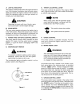
1. Unfasten the air cleaner cover retaining knob and remove the air cleaner cover (See Figure 23). 2. Remove the foam precleaner by sliding it up off the paper element (See Figure 23). 3. Remove the wing nut and element cover plate, then lift out the paper air filter element. 4, Do not wash the paper element or use pressurized air, as this will damage the element. Replace a dirty, bent or damaged element. Handle new elements carefully; do not use if the sealing surfaces are bent or damaged.
SPARK PLUG HEADLIGHTS Refer to SPECIFICATIONS when head lamp bulbs is necessary. replacement of WARNING To avoid possible injury, be sure the engine is off and has cooled before making any adjustments or repairs. I WARNING Allow the engine and surrounding surfaces to cool before changing the head lamp bulbs. Replace headlight bulbs as follows: (See Figure 25) NOTE 1. Remove all dirt from around the spark plug before removing.
FUSES MAINTENANCE Always use the same capacity fuse for replacement. Refer to SPECIFICATIONS. If the electrical system does not function, check the fuses. The tractor is shipped with a wet battery --the battery acid has already been added and the battery sealed. Although the battery is maintenance free, the following care should be taken when handling the battery and to assure its proper life cycle. To replace a fuse, pull the old fuse from the fuse holder and install the new fuse.
BATTERY REMOVAL OR INSTALLATION 5. Lift the battery upward and remove from the left side of the tractor. WARNING When removing the battery, disconnect the battery cables in the following order to avoid arcing and the resulting sparks: STRAP Battery Removal: 1. Disconnect the Negative cable. 2. Disconnect the Positive cable. Battery Installation: 1. Connect the Positive cable. 2. Connect the Negative cable. MOUNTING ROD To replace the battery, proceed as follows: 1.
TIRES MOUNTING TIRES ON THE RIM Keep the pneumatic tires properly inflated. Overinflation will cause operator discomfort. Under-inflation will cause short tire life. WARNING Do not mount a tire unless you have the proper equipment. Do not inflate the tire above the recommended pressure. Do not stand over the tire assembly when inflating. Accidental over inflation could cause an explosive separation of the tire and rim, which could result in serious injury of death.
SECTION V. MOWER This section contains adjustment, removal, installation, and maintenance information for the 44-inch mower deck. Instructions for installation and removal of the optional mulching plug are located at the end of this section. A. ATTACH I SPRING _" LIFT ASSIST _ _---_ LIFT ASSIST SPRING _<. NOTE The following step 1 applies only if the lift assist spring has been factory installed. If the spring was not installed, proceed to step 2.
, I 7. NOTE Check the tires for proper inflation before making a leveling adjustment. To level the deck, the tractor and deck MUST be placed on a hard, level surface during adjustment. SIDE-TO-SIDE 1, 2. 3. 4. Lower the deck onto the hard, level surface. Side-to-side leveling is obtained utilizing the adjustment ferrule and right hand hanger bracket (Refer to Figure 33). RH HANGER UPPER JAM NUT LEVELING ADJUSTMENT Position the tractor and mower deck on a hard, level surface.
, Initially adjust the front lift rod to allow approximately 5/8 inch of thread to protrude beyond both lock nuts of the front lift rod/bracket assembly (Refer to Figure 35). I The front lift rod must be against the front of both slots in the deck front roller bracket. If one FRONT LIFT ROD BRACKET side of the rod is not against the front of the slot after attaining the correct front pitch to the deck, tighten the front lock nut on that side until the rod just contacts the front of the slot.
CUTTING HEIGHT ADJUSTMENT washers. Remove the lock nuts, shoulder screws, and bell washers fastening the front ball wheels to the deck gauge wheel brackets. C, The mower can be set in multiple positions. NOTE: If multiple settings are used while mowing, it may be necessary to adjust the gauge wheels for each setting to prevent scalping. Again place the tractor implement lift handle in the normally desired mowing height setting. SHOULDER SCREW F, .
, 4, While lowering the rear end of the lift assist rod, guide the lower spring hook into the pigtail hook at the lower front of the fender (See Figure 39). , Remove the rearward end of the PTO belt from the upper pulley of the deck center double-pulley (See to Figure 41). Engage the deck idler arm lever back into its stop bracket (Refer to Figure 40).
12. From the front of the tractor, push downward and hold the tractor quick-attach rod. Pull the front lift rod/bracket assembly forward to release the shoulder bolts on each side of the bracket from the © PTO BELT left and right tractor latch receivers. Release the tractor quick-attach rod.
INSTALLATION OF DECK , Make sure the slot in both rear deck brackets aligns with the implement lift link on each side of the tractor (Refer to Figure 49). WARNING Before performing the mower deck installation, place the PTO switch in the "OFF" position, engage the brake pedal lock, turn the ignition key to the "OFF" position and remove the key from the switch. Disconnect the spark plug wires for additional safety.
/ REAR DECK @ QUICK A'rI'ACH ROD Figure 53 FRONT LIFT ROD/ BRACKET ASSEMBLY Carefully guide the tractor implement lift links (left and right) into the rear deck bracket slots (left and right) as the tractor implement lift handle is lowered to its lowest setting (Refer to Figure 54). 7, Figure 51 While holding the front lift rod up, slide the mower deck forward until the rod aligns with both front roller bracket slots.
, From beneath the right rear fender, push the lift assist rod down and outward to release from the WARNING frame. Disengage the hook of the lift assist spring from the pigtail hook (See Figure 55). The deck idler arm lever is spring loaded. Release it slowly. LIFT SPRING 12. Disengage the deck idler arm lever from its stop bracket and release the spring tension by rotating the lever out and rearward (Refer to Figure 58). _[_ LEVER STOP y,__J. BRACKET PI6 ROD HOOK Figure 55 10.
14. Twist the PTO belt 1/4 turn to engage the narrow sides of the belt into the grooves of the two tractor front-lower pulleys (Refer to Figure 60). LEVER STOP ;KET © PTO BELT @ TRACTOR FRONT LOWER PULLEYS IDLER ARM LEVER FRONT LIFT ROD/BRACKET. ASSEMBLY Figure 62 18. Connect the spark plug wires if disconnected. D. MAINTENANCE Figure 60 CLEANING AND BLADE CARE 15. From the front of the tractor, push the PTO belt through the front lift rod, then to the center of the deck.
maintained. If the cutting edge of a blade has been sharpened to within 5/8 inch of the wind wing radius (see Figure 63), it is recommended that new blades be installed. New blades are After every 10 hours of operation and/or before putting the deck into winter storage, lubricate the spindle assemblies and the spindle belt idler arms using 251H EP grease or an equivalent No. 2 multipurpose lithium grease. Excess grease will be expelled from the upper spindle seals.
6. Reinstall the spindle belt covers. 7. Engage the idler arm lever into its stop bracket. , 5 Position the mulching plug so that the retaining lip on the backside of the plug partially interlocks with the lower edge of the deck chute opening; then rotate the top of the plug upward so that the hooks engage the deflector hinge rod (See Figure 67). 4, Push the mulching plug fully downward and lower the chute deflector. 5.
SECTION VI. OFF-SEASON If the machine is to be inoperative for a period longer than 30 days, the following procedures are recommended: STORAGE Drain fuel into an approved container outdoors, away from open flame. a. Drain any large volume of fuel from the tank by disconnecting the fuel line from the in-line fuel filter near the engine.
SECTION VII. MOWING MOWING WARNING To avoid possible injury, do not allow anyone in the area opposite the discharge chute while mowing. Although the area has been supposedly cleared of foreign objects, small objects may be picked up and discharged by the mower. WARNING Never direct the discharge of material toward bystanders or allow anyone near the machine while in operation. For best results it is recommended that the first two laps should be cut with the discharge thrown towards the center.
OPTIONAL EQUIPMENT When you purchased your tractor, you probably had it completely equipped for your particular needs at the time. However, later you may wish to obtain optional equipment or accessories. These items and other allied equipment can be purchased from, and installed by, your authorized Cub Cadet dealer.
MAINTENANCE Operation to be performed Before each use Clean grille, engine air inlet screen, dash intake screen and side 30 hours or 50 hours 100 hours or once a month three times a season or twice a season or yearly Before storage X X X Change engine oil & oil filter After first 5 hours Check transmission oil level X Replace transmission oil filter 10 hours More often under dirty conditions panel screens Check engine oil level Fill fuel tank CHART More often under dirty conditions X
TROUBLESHOOTING Possible Cause Possible Remedy HARD TO START No gasoline in fuel tank or carburetor ..................... Fill the tank with gasoline. Check the fuel line, carburetor and fuel filter. Fuel line or carburetor clogged ................................ Clean the fuel line and carburetor carburetor cleaner. Fuel filter plugged .................................................... Replace. Water in gasoline .....................................................
TROUBLESHOOTING Possible Cause Possible Remedy LACK OF POWER Air cleaner clogged ................................................. Service the air NANCE." cleaner element. Refer to "MAINTE- Engine overload ...................................................... Reduce the load. Engine overheated .................................................. Make sure the air intake screen, shrouding, engine fins, side panels, dash intake screen and grille are free of accumulated dirt and debris.
LUBRICATION Point of Lubrication Check at Hours Change at Hours TABLE Anticipated Air Temperature Capacity Above + 32°F Cub Cadet Engine Oil SAE 1OW3Oor 1OW4O Below + 32°F Cub Cadet Engine Oil SAE 5W20 or 5W30 Engine crankcase Check before each use 100 Approx. 4 pints Hydro transmission and transaxle with filter Check before each use Add as needed Approx. 6 qts Steering knuckles and front axle pivot bolt 10 Use 251H EP grease or equivalent No.
LUBRICATION GUIDE WARNING The service life and reliability of any machine depends upon the care it is given. Proper lubrication is a very important part of that care. This lubrication schedule reflects the minimal requirements to maintain the equipment. More frequent inspections and maintenance is preferable. NOTE: We do not recommend the use of a pressure washer or garden hose to clean your unit. They may cause damage to electrical components; spindles; pulleys; bearings; or the engine.
LUBRICATION --Before GUIDE Each Use 1. Engine filler cap and dipstick Check the oil (with the engine stopped) and add sufficient new oil to bring it to the "FULL" mark on the dipstick. Do not overfill. Do not operate the engine if the oil level is below the "LOW" mark on the dipstick. 2. Transmission oil level Check the oil with the engine stopped. Keep the lubricant up to the "FULL" mark on the dipstick. and fill port NOTE: The transmission oil level and fill port services the following: 1.
m12 12 m CHECK OIL LEVEL BEFORE EACH USE ol o [] -- 14 LEFT SIDE CHECK OIL -2 LEVEL BEFORE EACH USE _ 10B--6 BOTH SIDES --13 BOTH SIDES rrl
SPECIFICATIONS 2186 CAPACITIES Fuel Tank ........................................................................ Crankcase (approximately) 2-1/8 gallons ............................................. Transmission Case (approximately) HYDROSTATIC DRIVE 4 pints ................................ 6 qts. Speed: Forward ................................................................ Reverse ................................................................ 0 to 6 mph 0 to 3 mph ENGINE Make and Model .....
USE THIS PAGE AS A GUIDE TO DETERMINE SLOPES WHERE YOU MAY NOT OPERATE SAFELY. SIGHT AND HOLD THIS LEVEL WITH A VERTICAL TREE A POWER POLE A CORNER OF A BUILDING I OR A FENCE POST "........ I A,. I "10 I I I I ,.,. 5" Illf _IIW ,1w ,,.,. ,, ,,,,I , rrl _' "0 15 ° P ,_ WARNING Do not mow on inclines with a slope in excess of 15 degrees (a rise of approximately 2-1/2 feet every 10 feet). A riding mower could overturn and cause serious injury.
CUB CADET CORPORATION MANUFACTURER'S ONE YEAR LIMITED WARRANTY (COMMERCIAL The limited warranty set forth below is given by CUB CADET CORPORATION ("CUB CADET") with respect to new merchandise purchased and used in the United States, its possessions and territories.
CUB CADET CORPORATION MANUFACTURER'S LIMITED (RESIDENTIAL The limited warranty set forth below is given by CUB CADET CORPORATION ("CUB CADET") with respect to new merchandise purchased and used in the United States, its possessions and territories. Batteries and belts are subject to separate terms as follows: d. Batteries have a one-year prorated limited warranty with 100% replacement during the first three months.
MAINTENANCE PARTS CHART MODEL 2186 SERIES 2000 18 HP KOHLER ENGINE OIL Engine Oil Requirements approx... Part No. 4 pints Cub Cadet engine oil Ambient temperature viscosity (Grade SG or SH) Above +32°F SAE 10W30 or 10W40 Below +32°F SAE 5W20 or 5W30 © AIR FILTER 737-3030A (10W30) 737-3049 (5W30) Part No. Air Filter Requirements Clean air filter per instructions in your Operator's Manual .... under Maintenance - Air cleaner.