
Instruction Manual

Electrical System
113
7. If the regulator/rectifier fails any one of these tests, replace it with a new one.
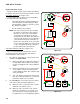
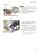
8. Check the D.C. amperage output of the regulator/rec-
tifier using an Ammeter of sufficient capacity or a
D.C. Shunt tool and a volt meter set to read on the
millivolt scale, as described in the TOOLS section of
this chapter.
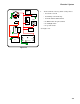
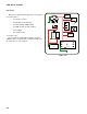
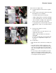
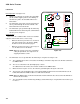
9. If the regulator/rectifier passes all of these tests, but
the battery is not charging, check the circuit between
the regulator/rectifier D.C. output (B+) terminal and
the battery positive post for voltage for a voltage
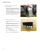
drop. See Figure 7.32.
• The harness connector, the 30A fuse, and the hot
post on the starter solenoid all lie between the reg-
ulator/rectifier and the battery.
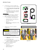
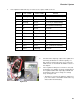
Test # Pos. Probe COM. Probe Results
1 Housing B+ O.L. (infinite resistance)
2 Housing A.C. 1 O.L. (infinite resistance)
3 Housing A.C.2 > 1.0 Ω (5 second delay)
4 B+ A.C.1 0 Ω (Perfect continuity)
5 B+ A.C.2 > 1.0 Ω
6 B+ Housing > 1.0 Ω
7 A.C.1 B+ 0 Ω (Perfect continuity)
8 A.C.1 A.C.2 > 1.0 Ω
9 A.C.1 Housing > 1.0 Ω
10 A.C.2 B+ O.L. (infinite resistance)
11 A.C.2 A.C.1 O.L. (infinite resistance)
12 A.C.2 Housing > 1.0 Ω
Figure 7.32