
Instruction Manual

2000 Series Tractors
112
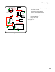
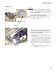
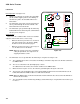
6. Regulator/rectifier check: See Figure 7.30.
6a. Check the ground.
• With the engine running and the stator leads re-
connected to the regulator/rectifier, perform a
ground-side voltage-drop test from the regulator/
rectifier to the engine block.
• If the voltage reading is greater than 0.1 Volts
D.C., replace or properly fasten the ground wire
that connects the regulator/rectifier to the engine
block. Retest to confirm good connection.
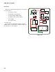
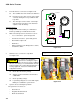
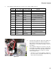
6b. Bench Test: See Figure 7.31.
• Set a digital multi-meter to read on the X100Ω
scale.
• With the key OFF and the fuse removed, unplug
all the wires from the regulator/rectifier.
• Remove the regulator/rectifier from the engine
(not strictly necessary, but provides easy
access).
• Make the resistance tests described in the
accompanying table.
• B+ is the D.C. terminal
• A.C.1 is the A.C. terminal nearest B+
• A.C.2 is the A.C. terminal furthest from B+
Figure 7.30
Figure 7.31
A.C.2 A.C.1 B+