Professional Shop Manual 2000 Series Tractors (2011 Model year and Newer) NOTE: These materials are for use by trained technicians who are experienced in the service and repair of outdoor power equipment of the kind described in this publication, and are not intended for use by untrained or inexperienced individuals. These materials are intended to provide supplemental information to assist the trained technician.
Table of Contents Chapter 1: Introduction Professional shop manual intent ........................................................................1 Fasteners ...........................................................................................................1 Assembly ...........................................................................................................3 Description of the 2000 series tractor ................................................................
Chapter 6A: Manual Steering Steering alignment ...........................................................................................67 Front wheels ....................................................................................................69 Front wheel bearings .......................................................................................70 Axles ................................................................................................................
Parallel ...........................................................................................................123 Series/parallel ................................................................................................124 Shorts .............................................................................................................124 Opens ............................................................................................................124 Increased resistance .................
Chapter 9: Maintenance intervals Lubrication .....................................................................................................179 Engine maintenance .......................................................................................179 The spark plugs .............................................................................................180 Air filter and pre-cleaner................................................................................. 181 Oil change ................
Introduction CHAPTER 1: INTRODUCTION Professional Shop Manual intent This Manual is intended to provide service dealers with an introduction to the electrical and mechanical aspects of the 2000 series tractor. • Detailed service information about the engine will be provided by the engine manufacturer. Disclaimer: The information contained in this manual is correct at the time of writing. Both the product and the information about the product are subject to change without notice.
2000 Series Tractors • Be prepared in case of emergency: ! CAUTION Keep a fire extinguisher nearby Keep a first aid kit nearby Keep emergency contact numbers handy • Replace any missing or damaged safety labels on shop equipment. • Replace any missing or damaged safety labels on equipment being serviced. • Grooming and attire: ! WARNING Do not wear loose fitting clothing that may become entangled in equipment. Long hair should be secured to prevent entanglement in equipment.
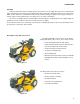
Introduction Assembly Torque specifications may be noted in the part of the text that covers assembly, they may also be summarized in tables along with special instructions regarding thread locking or lubrication. Whichever method is more appropriate will be used. In many cases, both will be used so that the manual is handy as a quick-reference guide as well as a step-by-step procedure guide that does not require the user to hunt for information.
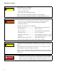
2000 Series Tractors Model and Serial Numbers The model and serial number tag can be found under the seat. See Figure 1.3. Model number Serial number The serial number is located to the right of the model number as shown above. See Figure 1.3. Figure 1.3 The model number is 14W-3AE-010. The break down of what the number mean is as follows: 14 ........................................Garden tractor .......W. .................................Sales revision ...........-. ...............................
Engine Related Parts CHAPTER 2: ENGINE RELATED PARTS This chapter covers the engine accessories that are manufactured by Cub Cadet. IMPORTANT: The engine is manufactured by Kohler. Refer to the Kohler manual for engine specific service information. Muffler To Remove/replace the muffler: 1. Remove the hood by following the procedures described in Chapter 4: Body. 2. Remove the screw that holds the conduit clamp to the heat shield using a 1/2” wrench. See Figure 2.1. 3.
2000 Series Tractors Fuel tank removal/replacement Remove/replace the fuel tank by following these steps: ! CAUTION Gasoline and its vapors are extremely flammable. Use common sense when working around the fuel system 1. Safely drain the gasoline from the fuel tank. 2. Disconnect the seat switch. See Figure 2.3. NOTE: On the GTX2154LE, it will be necessary to cut the wire tie that holds the seat switch connector to the seat frame.
Engine Related Parts NOTE: On the GTX2154LE: • Remove the four screws, indicated by the arrows in Figure 2.5, that hold the seat frame to the fender using a 7/16” wrench. • Remove the two screws that hold the rear of the fender to the frame using a 7/16” wrench. Figure 2.5 On manual deck lift models: 5. Grip Remove the deck lift lever grip. See Figure 2.6. NOTE: A blow-gun with air pressure regulated to less than 25 PSI (1.
2000 Series Tractors 9. Unthread the fuel cap. 10. Pull the fuel cap tether retainer out of the fuel tank using a long pair of pliers. See Figure 2.8. NOTE: The fuel cap tether is mandated by the EPA. If it is broken, the fuel cap must be replaced. Tether Figure 2.8 11. Gently pry out the barbed fasteners that hold the end of the running board mats to the fender. See Figure 2.9. Barbed fasteners Figure 2.9 12. Remove the six nuts and bolts, indicated by the arrows in Figure 2.
Engine Related Parts 14. Re-install the fuel cap. 15. Disconnect the vent hose from the roll over valve. See Figure 2.11. Roll over valve Vent hose Figure 2.11 Roll out 16. Roll the fuel tank towards the rear of the tractor until it is free from the tractor. See Figure 2.12. 17. Disconnect the fuel line from the fuel tank. 18. Install the fuel tank by following the previous steps in reverse order. 19. Test run the tractor in a safe area before returning it to service. Figure 2.
2000 Series Tractors Throttle cable adjustment If the engine does not achieve its high (no load) speed when the throttle is moved to the full throttle position, check the cable adjustment before performing any other engine or carburetor inspections. To adjust the throttle cable: 1. Raise the hood and locate the engine control panel. 2. Operate the throttle lever while observing its direction of movement. See Figure 2.13. 3. Loosen the screw that secures the throttle cable clamp. 4.
Engine Related Parts Choke and Throttle levers and cables To remove/replace levers and cables: NOTE: The choke and throttle cables must be removed with the lever assemblies before they can be separated and replaced. 1. Remove the dash by following the procedures described in Chapter 4: Body. 2. Remove the three screws that secure the control lever assemblies in place using a 3/8” wrench. See Figure 2.15. 3. Rotate the levers while pulling the assemblies out of the dash. 4.
2000 Series Tractors 6. On the side of the lever assembly that has the slot, lift the shaft that the levers pivot on enough to slide the spring off. See Figure 2.18. 7. Slide the lever assembly toward the side with the slot until the assembly clears the other side. Spring Slot Figure 2.18 8. Slide the levers off of the indexing plate. See Figure 2.19. 9. Install the levers and cables by following the previous steps in reverse order. Indexing plate Figure 2.
Engine Related Parts Engine removal/installation Fuel pump It may be necessary to remove the engine to perform engine repairs such as replacing the ignition coil, flywheel, alternator or to work on the cylinder heads. To remove the engine: 1. Remove the hood by following the procedures described in Chapter 4: Body. 2. Disconnect the negative battery cable from the battery. 3. Remove the muffler by following the procedures described in the muffler section of this chapter. 4.
00 Series Tractors 10. Remove the dash by following the procedures described in Chapter 4: Body. 11. Disconnect the drive shaft from the engine by removing the four patch bolts using a 7/16” wrench. See Figure 2.23. Drive shaft Figure 2.23 12. Remove the four nuts and bolts, indicated by the arrows in Figure 2.24, that hold the engine to the sub frame using a pair of 9/16” wrenches. Figure 2.24 13. Attach a lift chain to the engine’s lifting points. See Figure 2.25.
Engine Related Parts NOTE: If the front drive shaft coupling comes apart: • Remove the engine. • Insert the rollers in between the drive shaft end and the coupler housing one at a time, until all eight are in place. See Figure 2.26. Blue rollers Figure 2.26 To install the engine: 1. Install an alignment stud into one of the drive shaft coupler holes on the engine. See Figure 2.27. NOTE: To make an alignment stud: See Figure 2.27. • Obtain a 1/4” x 20 bolt that is a minimum of 4” long.
2000 Series Tractors 8. Install the engine mounting nuts and bolts. 9. Remove the engine lift chain. 10. Install the dash by following the steps described in Chapter 4: Body. 11. Install the starter. 12. Reconnect the starter wires. 13. Reconnect the engine harness. 14. Reconnect the ground cable to the base of the engine. 15. Reconnect the fuel line to the fuel pump. 16. Install the muffler by following the procedures described in the muffler section of this chapter. 17.
Brakes CHAPTER 3: BRAKES Brake adjustment The transmission on the 2000 series tractor is driven by a Hydro-Gear BDU-10L pump. The pump will provide the braking action when it is in operation. There is a mechanical brake on the side of the transmission. This brake is used primarily as a parking brake. It is also used as a back up brake in case of a failure of the hydro pump. The operation of the brakes should be tested before performing any adjustments. To test the operation of the brakes: 1.
2000 Series Tractors • The rod that connects the clutch/brake latch plate to the heavy brake actuator spring should not droop. See Figure 3.3. • Check the brake pedal shaft bushings for wear. No droop Figure 3.3 Adjust the brakes by: NOTE: The brake is located between the frame and the transmission on the right side of the tractor. It is a tight fit, but it can be reached from the under side of the tractor aft, of the rear axle. 0.010” feeler gauge NOTE: In Figure 3.
Brakes Brake puck/rotor replacement On transmission used on the 2000 series tractor, the brake pucks are wearing parts that will need to be serviced from time to time. If the tractor is operated with the parking brake dragging, the pucks will wear out rapidly and the brake rotor will develop hot spots. If the tractor is operated long enough, the rotor may have grinding marks on it with excessively worn pucks.
2000 Series Tractors 6. With the caliper on a work bench, remove the brake puck, backing plate and the two brake pins. See Figure 3.7. 7. Inspect all the components of the brake assembly for damage or wear: brake pads, puck plate, actuator pins, actuator arm, anti-rotation bracket, yoke, torsion spring, flat washer and locking hex nut. 8. Check for free movement of the brake pins. A dry lubricant can be used on the brake pins sparingly.
Brakes Brake shaft assembly To remove/replace the brake shaft: 1. Remove the cutting deck by following the procedures described in Chapter 8: Cutting Decks and Lift shaft. 2. Lift and safely support the tractor. 3. Remove the forward drive pedal shaft by following the procedures described in Chapter 5: Drive System. 4. Disconnect the brake pedal by removing the two nuts and bolts that attach it to the brake pedal shaft using a pair of 1/2” wrenches. See Figure 3.10. 5.
2000 Series Tractors 8. Slide the brake pedal shaft to the left enough for it to clear the frame on the right side. 9. Lower the shaft enough to gain access to the cotter pin that secures the brake rod to the pedal shaft. 10. Remove and discard the cotter pin. See Figure 3.13. 11. Remove the pedal shaft from the tractor. 12. Install the brake pedal shaft by following the previous steps in reverse order.
Brakes Brake rod adjustment NOTE: The brake rod should not come out of adjustment on its own. If the brake rod does need to be adjusted, check for a bent rod, worn bushing and worn brake pucks. E-ring To adjust the brake rod: Figure 3.14 1. Remove the cutting deck by following the procedures described in Chapter 8: Cutting Decks and Lift Systems. 2. Lift and safely support the tractor. 3. Remove the E-ring and washers from the right side of the forward drive pedal shaft. See Figure 3.14. 4.
2000 Series Tractors 8. Loosen the jam nut. See Figure 3.17. 9. Tighten or loosen the ferrule as needed so that it aligns with the hole in the bell crank of the brake pedal shaft with no slack in the brake spring. 10. Tighten the jam nut. 11. Attach the brake rod to the brake pedal shaft. NOTE: The cotter pin that secures the brake rod to the pedal shaft can be replaced with a bow tie clip (714-04040). 12. Slide the brake pedal shaft to the right until it stops. 13.
Body CHAPTER 4: BODY What is covered by this chapter The intent of this chapter is to describe the removal and disassembly of the major body panels on the tractor. • Hood • Seat • Fenders • Dash panel NOTE: It is not absolutely necessary to remove the mowing deck for any procedures covered in this section. The technician may choose to remove the mowing deck so that it is easier to reach some parts of the tractor. Hood Hood removal: Lift here 1. The hood is front-hinged. See Figure 4.1. 2.
2000 Series Tractors 4. The hood hinges on a pair of shoulder bolts that fit into slots in the hood bracket. 5. The hinge travel is limited by a tab that fits into a channel in the hood bracket. 6. Open the hood far enough to align the tabs with the slots, then lift the hood off of the tractor. See Figure 4.3. Slot Figure 4.3 Hood components: side vent removal 1. Carefully pry the vent free of the lock tabs. 2. Pull the vent out of the hood assembly. 3.
Body Hood components: Headlight removal 1. With the spade terminals disconnected, rotate the lamp holder (socket) to release it from the grille assembly. See Figure 4.5. Figure 4.5 LED headlight assembly NOTE: The GTX2154LE has a LED headlight assembly. It is removed the same way as the incandescent headlight assemblies. Figure 4.6 Single-pin 1156-style lamp 2. Socket Rotate the bulb to release it from the socket. See Figure 4.7. NOTE: The LED assembly does not come apart. 3.
2000 Series Tractors Hood components: grille removal 1. Remove the hood assembly from the tractor, and place it on a stable work surface. 2. Disconnect the wires from the headlights. 3. Remove the two screws, one in each headlight housing, that hold the upper corners of the grille to the hood using a 5/16” wrench. See Figure 4.8. Screw + washer Figure 4.8 4. Remove the four screws, indicated by the arrows in Figure 4.9, using a 3/8” wrench. 5. Slide the heat shield out of the hood. Figure 4.
Body 6. Remove the two screws that hold the pivot bracket and grille to the hood assembly using a 3/8” wrench. See Figure 4.10. 7. Unlatch the tabs, where the screws were in step 3, while pushing the grille out of the hood. 8. Once removed, the headlight lens may be removed for cleaning by carefully prying the two lock tabs at the inner edge. See Figure 4.11. Screws Figure 4.10 Locating tab Lock tabs NOTE: The locating tab at the outer edge of each lens has no locking feature. 9.
2000 Series Tractors Hood components: pivot bracket removal 1. Remove the hood assembly from the tractor, and place it on a stable work surface. 2. Remove the four screws, indicated by the arrows in Figure 4.12, using a 3/8” wrench. 3. Slide the heat shield out of the hood. Figure 4.12 4. Remove the two screws that hold the pivot bracket and grille to the hood assembly using a 1/2” wrench. See Figure 4.13. Screws Figure 4.13 5. Remove the four screws, indicated by the arrows in Figure 4.
Body Fender and running board On the Cub Cadet 2000 series tractor, the fender and the running board are two pieces. It may be necessary to remove the fender and running board to gain access to items such as the deck lift shaft When removing the fender and running board, it is generally easier to remove both of them as one piece. NOTE: When working on the fuel tank, only the fender needs to be removed. To remove/replace the fender: 1. Disconnect the seat switch. See Figure 4.15.
2000 Series Tractors NOTE: On the GTX2154LE: • Remove the four screws, indicated by the arrows in Figure 4.17, that hold the seat frame to the fender using a 7/16” wrench. • Remove the two screws that hold the rear of the fender to the frame using a 7/16” wrench. Figure 4.17 On manual deck lift models: 4. Remove the deck lift lever grip. See Figure 4.18. NOTE: A blow-gun with air pressure regulated to less than 25 PSI (1.
Body 7. Unthread the fuel cap. 8. Pull the fuel cap tether retainer out of the fuel tank using a long pair of pliers. See Figure 4.20. NOTE: The fuel cap tether is mandated by the EPA. If it is broken, the fuel cap must be replaced. Tether Figure 4.20 9. Remove the reverse drive pedal using a 9/16” wrench. See Figure 4.21. 10. Remove the forward drive pedal using a 9/16” wrench. Forward pedal Reverse pedal Figure 4.21 11.
2000 Series Tractors 12. Gently pry up the rubber foot pad on one side of the tractor enough to gain access to the screw under it. See Figure 4.23. 13. Remove the screw using a 1/2” wrench. 14. Repeat steps 10 & 11 on the other side of the tractor. Rubber foot pad Screw Figure 4.23 15. Remove running board brackets by removing the two screws, indicated by the arrows in Figure 4.24, that hold each of them to the frame using a 1/2” wrench. 16.
Body Dash Panel The dash panel may be removed to provide access to the tilt steering column, power steering, or to replace the dash or dash support brackets. Cover 1. Remove the steering wheel 1a. Remove the cover from the center of the steering wheel. See Figure 4.26. 1b. Remove the bolt that holds the steering wheel to the steering shaft using a 1/2” wrench. 1c. Lift the steering wheel off of the shaft. 2. Disconnect the negative battery cable. 3.
2000 Series Tractors 7. Disconnect the PTO switch. See Figure 4.29. 8. Disconnect the hour meter. Hour meter PTO switch Figure 4.29 9. Remove the two screws, indicated by the arrows in Figure 4.30, that hold the left side of the dash to the dash support bracket using a 3/8” wrench. Figure 4.30 10. Remove the two screws that hold the right side of the dash to the dash support bracket using a 3/8” wrench. See Figure 4.31. Screws Figure 4.
Body 11. Remove the two screws, indicated by the arrows in Figure 4.32, from the bottom of the operators side of the dash using a 3/8” wrench. Figure 4.32 12. Remove the two screws, indicated by the arrows in Figure 4.33, that holds the base of the left side panel to the frame using a 1/2” wrench 13. Lift up on the dash enough to disconnect the RMC module and the key switch. 14. Lift the dash panel off of the tractor. 15. Assembly notes: • Assemble tractor by reversing the disassembly process.
2000 Series Tractors 38
Drive CHAPTER 5: DRIVE SYSTEM Transmission fluid filter The oil filter should be changed every 100 hours. NOTE: The filter can be changed without draining all of the transmission fluid. To change the transmission fluid filter: Anti-sway rod 1. Remove the deck as described in chapter 8: Cutting Decks and Lift Systems. 2. Lift and safely support the rear of the tractor. 3. Remove the nut that secures the anti-sway rod to the transmission torque bracket. See Figure 5.3. 4.
2000 Series Tractors Transmission fluid change NOTE: The transmission is filled with a high quality, specially blended oil. It only needs to be changed if it is contaminated. To change the transmission fluid: 1. Remove the deck as described in chapter 8: Cutting Decks and Lift Systems. 2. Lift and safely support the rear of the tractor. 3. Clean the transmission around the drain plug area. 4. Remove the drain plug using a 16 mm wrench. See Figure 5.1. 5. Remove the dip stick. 6.
Drive Drive shaft Hydro pump To remove/replace the drive shaft: 1. Remove the deck as described in chapter 8: Cutting Decks and Lift Systems. 2. Remove the dash by following the procedures described in Chapter 4: Body. 3. Remove the fender and running board by following the procedures described in Chapter 4: Body. 4. Remove the four screws that attach the drive shaft to the hydro pump using a 7/16” wrench. See Figure 5.4. 5.
2000 Series Tractors Hydro neutral control adjustment NOTE: Neutral control rarely goes out of adjustment on its own. If it needs adjustment, check for damaged linkage or signs of tampering. ! CAUTION The tractor’s engine and drive system must be operated to complete this procedure. Confirm that no hazards will be incurred by running the engine or operating the drive system. • Work in a well vented area to prevent carbon monoxide poisoning or asphyxiation.
Drive 4. Start the engine and advance throttle to maximum RPM. 5. Release the parking brake. 6. Watch both rear tires for movement. See Figure 5.8. NOTE: If there is no wheel movement, the hydro pump is in neutral and doesn’t need to be adjusted. Skip to step 14. NOTE: If one or both rear wheels move, the hydro pump needs to be adjusted. Figure 5.8 To adjust the hydro pump: 7. Turn off the engine. 8. Loosen the two screws, indicated by the arrows in Figure 5.
2000 Series Tractors Transmission removal/replacement To remove/replace the transmission: 1. Remove the deck as described in Chapter 8 Cutting Decks and Lift Shaft. Anti-sway bar NOTE: If the transmission is being removed to open it up, drain the fluid at this point by following the procedures described in the transmission fluid change section of this chapter. 2. Lift and safely support the rear of the tractor. 3. Remove the nut that secures the anti-sway rod to the transmission torque bracket.
Drive 5e. Disconnect the brake rod from the brake pedal shaft by removing and discarding the cotter pin. See Figure 5.14. 5f. Pull back on the brake rod and maneuver it past the brake shaft and forward drive shafts. 5g. Unhook the brake rod from the brake spring. Cotter pin Figure 5.14 Bow tie clip Brake pedal shaft Brake rod 6. Remove the drive control rod: 6a. Remove the bow tie clip that holds the drive control rod and spring to the bell crank on the pedal shaft. See Figure 5.15. 6b.
2000 Series Tractors 7. 8. Remove the by-pass rod: 7a. Remove the bow tie clip. See Figure 5.17. 7b. Slide the by-pass rod out the rear of the tractor. Remove the rear wheels by removing the four lug nuts that secure each wheel to the hubs using a 3/4” wrench. By-pass rod Figure 5.17 9. Drive shaft Remove the four bolts that attach the drive shaft to the hydro pump using a 7/16” wrench. See Figure 5.18. Figure 5.18 10.
Drive 11. Support the transmission with a transmission jack to prevent it from falling while the mounting bolts are removed. Saddle to hold transmission The transmission is very front heavy and can not be balanced on ! CAUTION a floor jack. The transmission will fall off of the jack as soon as the torque bracket clears the frame. Use of a transmission jack or a saddle made to fit this transmission and mounted onto a floor jack will help prevent this from happening. Figure 5.20 12.
2000 Series Tractors Forward drive pedal shaft To remove/replace the forward drive pedal shaft: 1. Remove the deck as described in Chapter 8: Decks and Lift Systems. 2. Remove the screw that holds the forward drive pedal to the pedal shaft using a 9/16” wrench. See Figure 5.21. 3. Unhook the forward drive pedal and remove it. Forward drive pedal Figure 5.21 4. Remove the E-ring and hex bushing from each end of the drive pedal shaft. See Figure 5.22.
Drive 7. While holding the drive control rod up and out of the way, slide the drive pedal shaft towards the left enough for the bell crank to clear the pin on the brake shaft’s bell crank. 8. Rotate the drive pedal shaft towards the rear of the tractor enough for the bell crank to clear the brake pedal shaft’s bell crank. 9. Remove the drive pedal shaft by sliding it towards the right enough for it to clear the hole in the frame. 10.
2000 Series Tractors Reverse drive pedal shaft To remove/replace the reverse pedal shaft: 1. Remove the deck as described in Chapter 8 Cutting Decks and Lift Shaft. 2. Remove the screw that holds the reverse pedal to the pedal shaft using a 9/16” wrench. See Figure 5.25. 3. Unhook the reverse pedal and remove it. Reverse pedal Figure 5.25 4. Remove the E-ring and washer from the right side of the forward pedal shaft. E-ring Figure 5.26 5.
Drive 6. Remove the E-ring and washer from the reverse pedal shaft. See Figure 5.28. 7. Slide the reverse pedal towards the right while sliding the forward pedal shaft left far enough for the nut and bolt of the roller to fit between the frame and the forward pedal’s bell crank. 8. Rotate the reverse shaft until its bell crank and rollers drop below the bell crank on the forward shaft. See Figure 5.29. 9. Remove the hex bushings. E-ring Figure 5.
2000 Series Tractors Transmission Disassembly NOTE: The transmission used on 2000 series tractors is driven by a Hydro-Gear BDU-10L-225 pump. The service procedures for that pump are available in Hydro-Gear service manual BLN-50327. 1. 2. 3. Drain plug Drain the oil from the transmission: See Figure 5.31. 1a. Clean the transmission around the drain plug area. 1b. Remove the drain plug using a 16 mm wrench. Leave the drain plug out.
Drive 5. O-rings Inspect the o-rings at the end of the hydraulic pick up tube. See Figure 5.34. NOTE: Two O-rings normally seal the lower end of the pick up tube. Figure 5.34 6. Remove the two screws that secure the brake assembly to the right transmission housing using a 3/ 8” wrench. See Figure 5.35. 7. Remove the brake disk from the output shaft. See Figure 5.36. Brake assembly Figure 5.35 Flange NOTE: The center flange of the brake disk faces outward. 8.
2000 Series Tractors 9. Remove and discard the output shaft seal from the right transmission case using a flat blade screwdriver. Output shaft Figure 5.37 10. Remove the four screws securing the front torque bracket, spacers and the pump to the transmission using a 1/2” wrench. See Figure 5.38. Torque bracket NOTE: The 3/4” spacers are located at the top, and the 3-1/2” spacers are located at the bottom. 11. Remove the front torque bracket, spacers and pump from the right transmission housing.
Drive Return to neutral bracket 13. Inspect the return to neutral bracket assembly. If the return to neutral bracket shows sign of wear or damage, it must be replaced. See Figure 5.40. NOTE: Neutral return adjustment will be necessary after the transmission assembly and installation sections have been performed. Figure 5.40 Patch bolt 14. Stand the transmission up on end so that the left hub is facing up. See Figure 5.41. 15.
2000 Series Tractors 18. Remove the fourteen screws securing the left transmission housing to the right transmission housing using a 1/2” wrench. See Figure 5.43. Left transmission housing Figure 5.43 19. Lift the left transmission housing off of the right transmission housing. See Figure 5.44. Figure 5.44 20. Lay the transmission down on the work surface. 21. Remove patch bolt and washer securing the right hub assembly to the right axle using a 1/2” wrench. 22.
Drive 24. Grasp the differential assembly and the output shaft. See Figure 5.46. Output shaft 25. Slowly pull the differential assembly and the output shaft out of the right transmission housing until the output shaft is clear of the transmission. 26. Remove the 54T bevel gear and thrust washer from the 9T output shaft. Differential Bevel gear NOTE: The differential ring gear fits into the output shaft, preventing it from being removed separately. Figure 5.46 27.
2000 Series Tractors 29. Remove the spacers from the differential axles. See Figure 5.49. Long spacer Short spacer NOTE: The short spacer goes on the axle towards the right (deep) housing, and the longer spacer goes on the axle towards the left (shallow) housing. NOTE: Mark the direction of forward rotation on the spur gear. This will keep the worn in teeth matched to the teeth on the output shaft. Figure 5.49 30. Secure the 60T spur gear in a soft jawed vice. See Figure 5.50. 31.
Drive 34. Lift the left axle, differential housing, 14T miter gear assembly off of the ring gear. 35. Separate the miter gear from the axle shaft by removing the pair of spiral lock rings. See Figure 5.52. Spiral ring Figure 5.52 Miter gear 36. Separate the differential assembly components and inspect for damage or wear. See Figure 5.53. Axle shaft Differential housing Spiral rings Figure 5.53 Ring gear Spider assembly 37.
2000 Series Tractors 40. Remove the oil filter from the right transmission housing using an oil filter wrench. See Figure 5.55. Oil filter Figure 5.
Drive Transmission Assembly Clean with alcohol Figure 5.56 1. Remove any excess sealant from the transmission housings mating faces. 2. Clean the mating faces of the transmission housings using a scrubbing pad and alcohol. See Figure 5.56. 3. Install a new oil filter onto the right transmission housing. 4. Secure the right axle, spiral retainer groove facing up, in the soft jawed vice. 5. Set the threaded differential housing over the right axle, cup facing up. 6.
2000 Series Tractors 20. Place a 3/16” bead of Loctite® Ultra Black or similar sealant around the perimeter of the right housing mating face. See Figure 5.58. 21. Slide the left transmission housing over the left axle assembly and set it into position, aligning the mounting holes with the threads. 22. Apply a small amount of releasable thread locking compound such as Loctite® 242 (blue) to the fourteen hex cap screws that hold the two transmission halves together. 23.
Drive 33. Secure the brake assembly to the right transmission housing with the hex cap screws using a 3/8” wrench. NOTE: Tighten the brake assembly hex cap screws to a torque of 80 - 100 in lbs (9 - 11 Nm). 34. Adjust the brake pad clearance by following the procedures described in Chapter 3: Brakes. 35. Rotate the transmission so the filter is facing up. 36. Insert the 13T input pinion, ball bearing and spring washer. 37. Lubricate the gland seal and insert it into the right transmission housing.
2000 Series Tractors Symptom Complete loss of drive Root problem Inoperative pedal linkage or control arm not moving trunnion shaft Visually inspect linkage and force-check the control arm/ trunnion connection. Loss of power to hydro pump Drive shaft and couplings to engine and Transmission Inspect and force -check drive shaft and coupling. May require drive shaft removal. Sheared input shaft at hydro pump Remove drive shaft and forcecheck input shaft (push/pull/ turn).
Drive Symptom Loss of drive in Reverse only Sluggish operation, no unusual noise Root problem Mechanical cause Recommended action Loss of hydraulic pressure in forward circuit Completely inoperative charge relief valve Remove and inspect charge check valves. Loss of control input Damaged Reverse pedal linkage Check the operation of the reverse pedal linkage. It transfers motion to the Forward pedal linkage. Low engine speed.
2000 Series Tractors Symptom Sluggish operation, hydraulic noise 66 Root problem Mechanical cause Recommended action Dragging brake Brake caliper not releasing Check the brake pedal and linkage to the brake caliper. Check brake adjustment. Check caliper operation. Entrained air in system Damaged pick-up tube or fitting leak at end of pick-up tube. Remove pick-up tube for inspection and replace O-ring seal. Bottom O-ring leak will leave a puddle under the tractor.
Manual Steering CHAPTER 6A: MANUAL STEERING Steering alignment NOTE: Before performing a front end alignment, check for wear or damage that might cause the misalignment of the front wheels: • Worn rod ends • Bent drag links • Loose steering arms or loose drag links • Worn axles or king pin bores • Worn wheel bearings • Lift the front axle and spin each front wheel to check for excessive run-out.
2000 Series Tractors 7. The measurement taken in front of the axle (B) should be between 1/16” and 1/4” less than the measurement taken behind the axle (A). If not, perform the following steps: Jam nut 8. Loosen the jam nut at the rear of the right spherical rod end using a 9/16” wrench and an 11/16” wrench. See Figure 6A.3. 9. Remove the nut, bolt and washer that secures the right spherical rod end to the right axle assembly using a pair of 9/16 wrenches. 10.
Manual Steering Front wheels Remove/ replace the front wheels: Hub cap 1 Lift and safely support the front end of the tractor. 2. Gently pry off the hub cap. See Figure 6A.4. Figure 6A.4 Cotter pin 3. Remove and discard the cotter pin. See Figure 6A.5. 4. Remove the washer. See Figure 6A.5. 5. Slide the wheel off of the axle. Washer Figure 6A.
2000 Series Tractors Front wheel bearings To replace the front wheel ball bearings: 1. Lift and safely support the front end of the tractor. 2. Remove the front wheel by following the procedures described in the previous section of this chapter. 3. Drive the bearings out of the wheel hub using a blunt ended punch. See Figure 6A.6. Ball bearing Figure 6A.6 4. Drive in the new bearings using a brass punch or a suitable bearing driver that contacts only the outer race. See Figure 6A.7. 5.
Manual Steering Axles NOTE: The axles used on the left side and right side are the same part number. Steering arm 1 Lift and safely support the front of the tractor. 2. Remove the front wheel by following the procedures described in the front wheel section of this chapter. 3. Support the axle while loosening the nut and bolt that hold the steering arm onto the axle using a pair of 1/2” wrenches. See Figure 6A.8. 4. Lift the steering arm off of the axle. 5. Slide the axle out of the pivot bar.
2000 Series Tractors Steering sector gear and steering pinion gear If you are replacing the steering sector gear or steering pinion gear, check the condition of both gears for any wear or damage. It may be wise to replace both as a set. If the steering gears show any unusual or accelerated wear, identify and correct the cause of the wear before replacing the gears. Possible causes of rapid wear include: • Worn steering housing bores. • Bent steering shaft. • Worn sector gear pivot shaft.
Manual Steering 8. Disconnect the drag links from the forward most holes in the sector gear using a 1/2” wrench and a 9/ 16” wrench. See Figure 6A.12. 9. Install the steering gears by following the previous steps in reverse order. Drag links NOTE: Apply a small amount of releasable thread locking compound such as Loctite® 242 (blue) to the sector gear bolt. 10. Inject grease into the grease fittings on the pivot bar and the steering housing. Figure 6A.12 11.
2000 Series Tractors Steering shaft To remove the steering shaft or to replace the hex bushing: 1. Remove the cutting deck by following the steps described in Chapter 8: Cutting Decks and Lift Shaft 2. Lift and safely support the front of the tractor. 3. Remove the flange lock nut securing the steering pinion gear to the steering shaft using an 11/16” socket. See Figure 6A.13.
Manual Steering NOTE: On tractors with power steering: • Loosen the lower nut and bolt of the steering shaft coupler using a pair of 1/2” wrenches. Steering shaft coupler • Remove the top nut and bolt from the steering shaft coupler. See Figure 6A.16. NOTE: It may be necessary to drive the bolt out with a punch. Figure 6A.16 6. Remove the two shoulder screws that hold the steering shaft collar to the tilt steering bracket using a 3/8” wrench. See Figure 6A.17. 7.
2000 Series Tractors 9. While holding the tilt steering bracket shoulder bolts with a 3/4” wrench, remove the lock nuts using a 9/ 16” wrench. See Figure 6A.19. NOTE: The threaded section of the shoulder bolts are a “D” shaft. Applying torque to the bolts will cause them to round over the “D” section, making it very difficult to get the bolt out. Shoulder bolt NOTE: On early production units, a large nut was used as a spacer on the right shoulder bolt. See Figure 6A.19. Figure 6A.
Manual Steering 10. Slide the tilt bracket up and towards the rear of the tractor enough that it clears the dash support tower. 11. Slide the tilt dampener off of the pin on the tilt bracket. 12. Lift the tilt bracket and steering shaft off of the tractor. NOTE: On tractors with power steering, it will probably be necessary to pry the steering shaft coupler off of the EPS assembly. Figure 6A.21 DO NOT hammer on any of the EPS components.
2000 Series Tractors Pivot bar 1. Remove the deck and PTO belt by following the procedures described in Chapter 8: Decks and Lift Systems. 2. Lift and safely support the front of the tractor. 3. Remove the axles by following the procedures described in the axle section of this chapter. 4. Slide the front deck link forward, out of the way. See Figure 6A.23. Front deck link Figure 6A.23 5. Support the pivot bar. 6. Remove the two travel stop bolts using a pair of 9/ 16” wrenches. See Figure 6A.
Manual Steering Steering housing To remove/replace the steering housing: 1 Remove the deck by following the procedures described in Chapter 8: Decks and Lift Systems. 2. Remove the dash by following the procedures described in Chapter 4: Body. 3. Remove the steering gears by following the procedures described in the steering gears section of this chapter. 4. Remove the steering shaft by following the procedures described in the steering shaft section of this section.
2000 Series Tractors Greasing the steering housing The steering housing should be greased every 25 hours. To grease the steering housing: 1. Lift and safely support the front of the tractor. 2. Inject grease into the grease fitting at the steering pinion gear until grease starts to ooze out. See Figure 6A.27. 3. Lower the tractor to the ground. Grease fitting Figure 6A.27 4. Open the hood. 5. Inject grease into the grease fitting at the steering housing pivot shaft until it starts to ooze out.
Electronic Power Steering CHAPTER 6B: ELECTRONIC POWER STEERING NOTE: The basic steering system, such as the tie rod ends, drag links axles, etc., are covered in Chapter 6A: Steering. In 2011, Cub Cadet introduced the Electronic Power Steering (EPS) system on the Cub GTX2154LE (50th anniversary edition) tractor. The EPS provides an electric assist to the steering wheel. The EPS is a system consisting of three sub-assemblies: the rubber torsion coupling, the EPS module and the EPS motor & gearbox.
2000 Series Tractors EPS motor & gearbox The steering input passes through the torsion coupling and module into the gearbox. The gearbox then passes the input force to the output shaft connected to the steering housing. The EPS motor assists in turning the input shaft by driving a set of planetary gears. The planetary gears drive a worm shaft. The worm shaft drives a worm gear on the output shaft.
Electronic Power Steering Troubleshooting the EPS The first step in troubleshooting the EPS system is to understand how it works. See Figure 6B.4. • A constant 12 volts is supplied by the battery through a 40 amp fuse in the fuse box. ,JQLWLRQ PRGXOH • The EPS is grounded through the green wire. • The EPS senses the ignition pulses from the ignition module primary windings through the yellow wire with a white trace.
2000 Series Tractors 7. Locate, but do not disconnect the EPS harness connector behind the battery. See Figure 6B.6. 8. Check for battery voltage at the red wire: 8a. Set the Digital Multi Meter (DMM) to the DC volts scale. 8b. Measure the battery voltage across the battery terminals NOTE: If the battery voltage is < 12.6 volts, charge the battery before continuing. 8c. Connect the black (-) lead of the DMM to the negative post of the battery. 8d.
Electronic Power Steering 9f. Without sitting on the tractor, turn the steering wheel a quarter turn back and forth. Watching the voltage reading on the DMM and the current reading on the amp clamp while doing this. NOTE: If the voltage drops below 13 volts and the current does not rise above 10 amps, repair the circuit suppling voltage to the EPS before proceeding with troubleshooting the EPS system.
2000 Series Tractors EPS motor To remove/replace the EPS motor and test it: NOTE: The EPS system comes with a 4 year warranty. DO NOT remove the EPS motor to test it within the warranty period. Outside of the warranty period, the EPS motor can be replaced separately from the EPS assembly. 1. Remove the EPS assembly by following the procedures described in the EPS removal section of this chapter. 2. Disconnect the EPS motor harness. 3. Remove the two screws, indicated by the arrows in Figure 6B.
Electronic Power Steering 8. Inspect the EPS motor gasket. If it is damaged, replace it. NOTE: Do not use a gasket sealant/adhesive on the EPS motor gasket. 9. Remove the sun gear from the EPS motor. Sun gear 10. Install the sun gear into the planetary gear set. Figure 6B.12 Harness EPS motor pig tail 11. Install the EPS motor. NOTE: While installing the EPS motor, align the motor pig tail with the EPS motor harness. 12.
2000 Series Tractors EPS removal/replacement 1. Open the hood. 2. Remove the battery: See Figure 6B.14. 2a. Disconnect the negative battery lead. 2b. Disconnect the positive battery lead. 2c. Remove the screw that secures the battery hold down to the battery tray using a 3/8” wrench. 2d. Swing the battery hold down out of the way. 2e. Remove the battery from the tractor. Battery Figure 6B.14 3. Remove the dash by following the procedures described in Chapter 4: Body. 4.
Electronic Power Steering Tappet wrench 6. Remove the EPS support bracket: 6a. Remove the two screws and washers that hold the support bracket to the EPS using a 1/2” wrench 6b. Remove the two nuts and bolts that secure the bracket to the dash support using a pair of 1/2” wrenches. NOTE: A thin wrench, such as a tappet wrench can be slid between the fender and the dash support to hold the bolt heads. See Figure 6B.17. 7. Slide the support bracket out of the tractor. Support bracket Figure 6B.17 8.
2000 Series Tractors Cruise control rod 12. NOTE: There is a spring attached to the cruise rod that will come off when the cotter pin is removed. 13. Spring Remove the cotter pin that secures the cruise control rod to the latch. See Figure 6B.20. Latch Remove the cruise control rod. Figure 6B.20 14. Remove the screws, two on each side of the tractor, that hold the dash support to the frame rails using a 1/2” wrench. See Figure 6B.21. Screws Figure 6B.21 15.
Electronic Power Steering 16. Loosen the top nut and bolt of the steering shaft coupler using a pair of 1/2” wrenches. 17. Remove the lower nut and bolt from the steering shaft coupler. See Figure 6B.23. Steering shaft coupler NOTE: It may be necessary to drive the bolt out with a punch. 18. Lift the dash support off of the tractor, taking the steering shaft with it. NOTE: It will probably be necessary to pry the steering shaft coupler off of the EPS. ! CAUTION Figure 6B.
2000 Series Tractors NOTE: Lift the EPS out of the tractor. NOTE: The EPS output shaft will pass through a spacer, washer and the steering housing. See Figure 6B.25. NOTE: Install the EPS by following the previous steps in reverse order. Spacer NOTE: The washer that goes in between the pinion gear and the steering housing, must be held in place under the tractor while inserting the EPS into the steering housing. 22. Washer Test drive the tractor in a safe area before returning it to service. Figure 6B.
Electrical System CHAPTER 7: ELECTRICAL SYSTEM Introduction This chapter is divided into four sections: • Section 1: About this chapter and precautions • Section 2: Components • This section will describe the location and operation of the electrical components on the mower. Where appropriate, some disassembly or component removal instructions will be included.
2000 Series Tractors Key switch The Key Switch is similar to those used in a variety of MTD applications since 1999. The difference, in this case, is that it is incorporated in the same housing as the RMC module. The two items are not available separately. See Figure 7.1. 1. RMC Module Front In the “OFF” position, continuity can be found between the M, G, and A1 terminals. See Figure 7.2.
Electrical System 3. 4. • Symptom: Crank, spark, but no fuel: First check the fuel tank to verify that there is fuel in it. If there is fuel in the fuel tank, test for power at the afterfire solenoid. If there is no power there, then check for continuity from B to A1 in the START position. If power is reaching the red wire that connects to the A1 terminal in the start position, the problem lies down stream of the key switch.
2000 Series Tractors RMC Module RMC Module The RMC Module is in the same housing as the key switch and is not available separately. For the purpose of diagnosis, it is treated separately. Diagnosis of the module with the key switch introduces too many over-lapping variables. See Figure 7.3. • Principle: To diagnose the module, the simplest approach is to check all of the inputs (safety circuits) that are connected to it.
Electrical System To identify a faulty RMC module: Purple If the RMC module does not function as described, the RMC plug test should be the first step in diagnosis. Green • If the RMC plug test confirms that the safety circuits (inputs) work as designed, yet the RMC module does not work properly, the RMC module is faulty. Yellow/White Red/Black Red • The RMC plug test will give an indication of what the problem is if it is not a faulty RMC module.
2000 Series Tractors Red wire with black trace • Behavior: There is a red wire with black trace between yellow wire with a black trace and the green wire. This wire provides the module with input from the reverse switch. When the mower is in reverse, this terminal should have continuity to ground. • Circuitry: This wire runs directly to the reverse safety switch. This is a simple metal tang switch that groundsout against the hydro control rod.
Electrical System PTO Switch Understanding the PTO switch Figure 7.6 3. 1. A-COM is in the starter inhibit circuit. It is a normally closed (NC) set of contacts. Power coming from the brake switch (key switch in START, brakes ON) flows through the orange wire with black trace to the PTO switch. When the PTO is OFF, and the contacts are closed, the power continues through the orange wire with white trace to the trigger terminal on the starter solenoid. 2. B-COM is in the PTO relay latch circuit.
2000 Series Tractors Reverse Safety Switch The Reverse Safety Switch is a simple metal tang switch mounted on a bell crank of the drive pedal shaft. When the reverse pedal is depressed, the bell crank will rotate towards the rear of the tractor, pressing the reverse switch into the hydro control rod. See Figure 7.8. Hydro control rod Reverse switch Figure 7.8 Seat Safety Switch The Seat Safety Switch is mounted inside the seat. It contains two sets of N.O. contacts See Figure 7.9.
Electrical System Seat circuit (GTX2154LE) Most seat switches that MTD use are NC switches. This means that when the operator leaves the seat, the switch closes, allowing a ground signal to pass through it. However, the 50th anniversary edition (GTX2154LE) is equipped with a special high back seat. This seat comes equipped with a SPST NO switch. This means that when the seat is empty, the switch is open, blocking the ground signal. Seat switch connector Figure 7.
2000 Series Tractors Starter solenoid On Kohler Command engines, the starter solenoid is part of the starter. See Figure 7.13. • Starter Solenoid When the proper safety conditions are met (brake applied, PTO OFF), the orange wire with white trace carries battery power to the engine harness connector. At which point the battery power is transferred to a blue wire that carries it to the trigger terminal of the solenoid. Figure 7.
Electrical System Start Circuit Turning the key to the START position: . # • spins the starter motor ! ' , 3 - . / ! • enables the ignition "RAKE 3WITCH $EPRESSED " • energizes the afterfire solenoid +EY 3WITCH 'ROUND Looking at the circuit that sends power to the starter motor: See Figure 7.16. 3YSTEM -ONITOR &USE 1. When the key switch is in the START position, battery power is passed from the B terminal to the S terminal. 2.
2000 Series Tractors Once the starter motor spins, we still need spark and fuel to make the engine run. Looking at the circuits that do that: 1. The ignition sparks are generated by an ignition module. The ignition module will work as long as the primary windings are not grounded. With the key switch in any position other than off, there is no connection between the M (Module) terminal and the G (Ground) terminal. See Figure 7.17.
Electrical System +EY 3WITCH h2EVERSE #AUTION -ODEv , 3 3YSTEM -ONITOR ! ' !FTERFIRE 3OLENOID ! " - 3. 04/ 3WITCH 'ROUND 'ROUND ! 04/ 2ELAY !T 2EST " # *URXQG 6ROHQRLG 6WDUWHU 0RWRU . # . / #/- 0/3 "ATTERY 237 'RND the afterfire solenoid • the windings of the PTO relay • the PTO switch C-COM terminal • the headlight switch • the system monitor (EADLIGHTS See Figure 7.19. ! PWR 3EAT 3W .
2000 Series Tractors Run Circuit +EY 3WITCH h2EVERSE #AUTION -ODEv With the key switch in the RUN position, the A1 terminal sends power to: , 3 • the afterfire solenoid • the windings of the PTO relay !FTERFIRE 3OLENOID ! " - 04/ 3WITCH 'ROUND the PTO switch C-COM terminal • the headlights • the system monitor " &USE # This is identical to what happens with the key in the START position, except that the circuit that actually spins the starter motor is not energized.
Electrical System Run Circuit / Reverse Caution mode +EY 3WITCH h2EVERSE #AUTION -ODEv , 3 3YSTEM -ONITOR ! ' With the key in Reverse Caution mode, A1 gets power from the B terminal, just like the normal run position. 2. In addition, A2 is internally connected to the L terminal. L is normally used for the lighting circuit. !FTERFIRE 3OLENOID ! " - 1. 04/ 3WITCH 'ROUND 'ROUND ! 04/ 2ELAY !T 2EST " &USE 2a. In this case, a separate lighting circuit draws power from A1 2b.
2000 Series Tractors Engine shut-down circuits Engine shutdown circuits stop the engine by disabling the ignition and removes power from the afterfire solenoid. .H\ 6ZLWFK * Key switch shut-down: See Figure 7.22. $IWHUILUH 6ROHQRLG % *URXQG )XVH 0DJQHWR The A1 terminal is de-energized. 6ROHQRLG NOTE: On older electrical system, prior to 2008, the afterfire solenoid was powered by the alternator.
Electrical System Charging circuit How it works Stator 1. When the engine is running, magnets attached to the underside of the flywheel induce A.C. (Alternating Current) in the stator that is mounted beneath the flywheel. See Figure 7.24. 2. The A.C. travels from the stator to and from the regulator/rectifier through the two white wires. NOTE: The magnets inside the flywheel act as a rotor for the charging system. Rotor (magnets in recess) Figure 7.24 3.
2000 Series Tractors 5. From the harness connector: See Figure 7.26. .H\ 6ZLWFK 5a. The red/white trace wire leads to the 20A fuse. 5b. From the fuse, the wire connects to the starter solenoid, sharing the “hot” post with the battery cable. 5c. 2. 3. / 6 0 $ % *URXQG $OWHUQDWRU 6WDWRU The shared post on the starter solenoid provides the final connection for the alternator output to reach the battery. )XVH 6WDUWHU 6ROHQRLG Testing Sequence: 1.
Electrical System 5. Figure 7.28 Stator check: See Figure 7.28. 5a. Key OFF, unplug the stator from the regulate/ rectifier. 5b. Check resistance through the stator using a digital multimeter set to read Ohms. • It should be between 0.1Ω and 0.14Ω. • A high reading indicates a fault in the windings. • A low reading indicates a short in the windings. • There should be a reading of O.L. (Open Line) between either lead and the engine block.
2000 Series Tractors 6. Regulator/rectifier check: See Figure 7.30. 6a. Check the ground. • With the engine running and the stator leads reconnected to the regulator/rectifier, perform a ground-side voltage-drop test from the regulator/ rectifier to the engine block. • If the voltage reading is greater than 0.1 Volts D.C., replace or properly fasten the ground wire that connects the regulator/rectifier to the engine block. Retest to confirm good connection. Figure 7.30 6b.
Electrical System 7. If the regulator/rectifier fails any one of these tests, replace it with a new one. Test # Pos. Probe COM. Probe Results 1 Housing B+ O.L. (infinite resistance) 2 Housing A.C. 1 O.L. (infinite resistance) 3 Housing A.C.2 > 1.0 Ω (5 second delay) 4 B+ A.C.1 0 Ω (Perfect continuity) 5 B+ A.C.2 > 1.0 Ω 6 B+ Housing > 1.0 Ω 7 A.C.1 B+ 0 Ω (Perfect continuity) 8 A.C.1 A.C.2 > 1.0 Ω 9 A.C.1 Housing > 1.0 Ω 10 A.C.2 B+ O.L.
2000 Series Tractors PTO Circuit .H\ 6ZLWFK ³5XQ´ Basic Operation: See Figure 7.33. 1. 3. • When the mower is put in Reverse, we want to turn off the blades unless the RevTec (RMC) module has been armed and engaged. When the operator leaves the seat for any reason, we want to turn off the blades. % & *URXQG 372 6ZLWFK 2Q )XVH 372 5HOD\ $W 5HVW 326 1(* *UQG %DWWHU\ 1 & There are some conditions when it is best to automatically turn off the mower deck to ensure safety.
Electrical System .H\ 6ZLWFK ³5XQ´ 2. $ * / 6 $ 372 &OXWFK $ % % 0 & 1 & 1 2 &20 *URXQG The seat switch contains two sets of contacts. The set with the yellow wire leads to ground when the contacts of the seat switch are closed. See Figure 7.34. 2a. When the operator leaves the seat, the seat switch connects the yellow wire to a ground path. 2b. That ground path passes through the RMC module to ground the PTO relay windings when the mower is put in reverse.
2000 Series Tractors Reverse Mower Control (RMC) circuit operation Historically, Cub Cadet residential mowers have not been able to mow in reverse. This has not been required by any laws or safety regulations, it was just safer for our customers and those around them. Then in 2005, ANSI regulations for residential mowers were changed, requiring that the mowing blades turn off when the mower was put in reverse. The new standard did allow for a user controlled over ride system.
Electrical System When the RMC module is armed and activated, it effectively disconnects the reverse switch from the circuit. See Figure 7.38. .H\ 6ZLWFK ³5XQ´ $ * / 6 $ The RMC module is disarmed and de-activated when the seat is vacated; it gets a ground signal through the second set of contacts in the seat switch.
2000 Series Tractors Deck lift circuit KDUQHVV FRQQHFWLRQ Basic Operation: See Figure 7.39. 1. Battery power goes through the top 30A fuse in the fuse box. It then flows through the orange wire until it reaches the deck lift harness connector. It then passes onto the red wire with a white trace. The red white with a white trace carries the power to the N.O. contacts of the deck lift relays. 2. Both of the deck lift relays have the N.C. contact connected to ground.
Electrical System Electrical diagnosis NOTE: Electrical diagnostic procedures and tools are the same for all Cub Cadet and MTD mowers. This section is written in a way to provide basic trouble shooting skills that can be used on any mower. With a basic understanding of the behavior of electricity and the tools used to measure that behavior, a technician can be about 80% effective at finding electrical problems.
2000 Series Tractors • Low Voltage: Many electronic devices simply stop working if system voltage falls below a given threshold. If a 12 volt system is run at 11 volts with a failing alternator, electronic controls may stop working. • Bad Grounds: Bad grounds can reduce the effective system voltage, create resistance and heat, and send false signals. This is the single most common breeding ground of electronic gremlins. • Heat and Vibration: Heat and vibration are hard on most mechanical devices.
Electrical System Ohm’s Law Ohm’s Law relates voltage, amperage, and resistance. It states that voltage is the product of resistance times current. • It is written as V = I x R. • In simplest terms, it goes like this: V • It takes 1 volt to push 1 amp through a resistance of 1 ohm (1 = 1 x 1). R I Figure 7.40 • This equation can be rearranged using algebra to solve for any one variable. • Those who were traumatized by algebra can represent Ohm’s law as a triangle.
2000 Series Tractors Kirchhoff’s voltage law Kirchhoff’s voltage law deals with voltage drops. A voltage drop is the amount of voltage used up or “dropped” by resistance in a circuit. Ohm’s law states that V = I x R, every component in a circuit has resistance, even the wires. To push current through resistance, it takes voltage. Kirchhoff’s voltage law states that the sum of all the voltage drops equals the source voltage.
Electrical System Types of circuits There are three ways a circuit can be wired: • Series • Parallel • Series/parallel Series Series circuits are wired so that the current has only one path to follow. If one component in the system fails, the circuit will be broken and whole system will not work. See Figure 7.43. Switch Lamp Battery Figure 7.43 Parallel Lamp Battery Parallel circuits are wired so that current has multiple paths to follow.
2000 Series Tractors Series/parallel Series/parallel circuits have some sections wired in series and some in parallel. See Figure 7.45. Lamp Battery Lamp Lamp Lamp Switch Figure 7.45 What can go wrong? There are three types of failures that can occur in an electrical circuit: 1. Shorts 2. Opens 3. Increased resistance Shorts A short is when electricity takes a path that it was not designed to take by-passing a component in the circuit.
Electrical System The Tools Equipment needed to diagnose an electrical system: • DMM (Digital Multi-Meter) • Wiring schematic or diagram Equipment that may be useful: • Fused jumper wires. • Test light • Self-powered continuity light • Ammeter • Battery charger • Battery tester • Battery jumper cables • Hand tools to gain access to components. • Flashlight.
2000 Series Tractors Digital Multi-meter A DMM is the most useful tool to troubleshoot any electrical system. There is an amazing variety of DMMs on the market. Some are very basic, others are tailored to specific industries, and some high-end graphing meters function like oscilloscopes. Even the most basic ones are quite versatile. See Figure 7.46. Uses Voltage Set meter to read “Volts DC (_ _ _)” if using an autoranging meter or to an appropriate scale (typically 20 Volts DC) if using a more basic model.
Electrical System Wiring diagram or schematic A wiring or a schematic diagram, and the ability to read it are very important in troubleshooting a circuit. The diagram shows how the circuit was designed and what paths the electricity is suppose to flow. Fused jumper wires Fused jumper wires are handy to help find bad grounds or to jump across switches for testing purposes. ! CAUTION Only use fused jumper wires.
2000 Series Tractors Ammeters and specialized charging system testers Inductive ammeters or “amp clamps” are available in many forms. Some are as simple as a gauge to be held against the circuit in question when it is energized. The operating principle is based on magnetic field induced by the current flow. See Figure 7.48. DMM with inductive ammeter feature Inductive ammeter There are two primary reasons to measure amperage. The first is to check the output of a charging system or battery.
Electrical System Batteries Batteries produce flammable and explosive gases, particularly during charging. ! CAUTION • Do not smoke or allow an open flame or heat source near the battery. • Charge batteries in an open area • Wear eye protection and acid resistant gloves when handling batteries. • Do not allow direct metal contact across the posts. This will produce extreme heat that may cause direct burns or ignite flammable gas.
2000 Series Tractors Checking battery condition There are three things to do when testing a battery: 1. • Visual inspection • Electrolyte test • Operational test Visual inspection • Inspect the battery and battery connections for corrosion. Clean if necessary. Neutralize acid with baking soda, and protect the terminals once they are cleaned. NOTE: Battery cable corrosion is the most common type of increased resistance circuit failures.
Electrical System Battery Testers There are four major ways to check a battery: • Electrolyte test using a specific gravity tester (hydrometer) to compare the density of the electrolyte in a fully charged battery to the density of water (water = 1.0 s.g.). • Electrolyte test using a refractometer to check the density of the electrolyte by measuring the degree to which light waves bend when passing through the electrolyte.
2000 Series Tractors Fixed load testers Fixed load testers (sometimes called toasters) are inexpensive load testers found at any auto parts store. See Figure 7.51. NOTE: Because they have a fixed load value, they do not give most batteries a reliable and safe load test. Most fixed load testers have a load that is more than 50% of the rated CCA of riding mower batteries. This makes them inappropriate to use on smaller pieces of outdoor power equipment.
Electrical System Battery discharge test Occasionally a battery will discharge while sitting unused. To test for a battery that is “leaking” voltage: Figure 7.53 1. Confirm that operator technique is not creating a situation that cases a draw. As an example, if a homeowner habitually turns their equipment off using a safety switch (perhaps vacating the seat with the key switch still ON), that may leave a relay or fuel shut-off solenoid energized. 2. Disconnect and charge the battery fully. 3.
2000 Series Tractors Electrical Troubleshooting 1. The first step in troubleshooting is to always verify the complaint. Defining and verifying the problem reduces the possibility of misunderstanding and helps clarify the diagnostic approach. 2. The next step is to check the simple stuff first: • Check the fuse or fuses: NOTE: Failure of any fuse is an indication that there is a problem of some sort in the circuit that the fuse protects. • Look for obvious physical damage.
Electrical System 6. Starting with a fully charged battery and battery cable connections that are clean and tight, measure the battery voltage. See Figure 7.54. 7. With the circuit energized, start at either end of the circuit and check for voltage. • If starting at the battery end of a powered circuit, trace it through until power vanishes. • If starting at the ground end of a powered circuit, trace it through to the point that power appears. Figure 7.
2000 Series Tractors Voltage Drop Test To review: • Ohm’s law states that it takes voltage to push current through a resistance. • Kirchhoff’s voltage law states that the sum of all the voltage drops equals the source voltage. • Combining those two laws, we see that any restriction in a circuit (e.g.: loose connector damaged wire, or corroded terminal) will use up some voltage as the current is pushed through. • A voltage drop test is a way of looking for that voltage.
Electrical System A similar ground-side test on a mower with a slowcranking starter motor can be conducted between the engine block and the negative battery post. See Figure 7.57. Figure 7.57 1. With the starter engaged, this machine exhibited a voltage-drop reading of 0.312 volts, indicating a poor ground connection. 2. Individually, these readings should lead a technician to inspect the connection between the solenoid and the ground path on the first mower (e.g.
2000 Series Tractors 6. 138 Voltage drop on a good circuit should be less than 0.1 volts. A voltage drop reading on the meter of greater than 0.2 volts indicates a fairly substantial problem that demands attention. • As an example, if the mower had a slow-turning starter, the ground-side voltage drop measured below 0.1 volts, and there was not a parasitic load on the engine (e.g. PTO clutch that is not fully disengaged), it would be logical for the technician to check voltage drop to the starter.
Electrical System Testing switches • Refer to the “COMPONENTS” section of this chapter that describes the function of the individual switches to be tested. • Switches can be tested “hot” by looking for voltage at the appropriate posts. This is not definitive, since the source of the voltage is not always confirmed. Checking for voltage does not work on switches that work by providing a ground path to the magneto primary windings or a solid state control device.
2000 Series Tractors Diodes • What is a diode? A diode acts like a one way valve, allowing current to flow in only one direction. See Figure 7.61. • Which way does this electrical check-valve work? There will be a band on one end of the diode. The band indicates the negative side of the diode • Most DMMs have the ability to test a diode. Silver band (-) (+) electrons flow from the negative to the positive. Figure 7.61 Testing a diode: 1. Isolate the diode in the circuit. 2.
Electrical System Continuity 5. There should be continuity. See Figure 7.63. 6. Switch the leads and repeat the test. 7. The meter should indicate no continuity. See Figure 7.64. 8. If the results do not match the above, replace the diode. Silver band (-) (+) Figure 7.63 No continuity Silver band (-) (+) Figure 7.
2000 Series Tractors Relay Most of the relays used by MTD or Cub Cadet have five pins. See Figure 7.65. • Windings: Terminals 1 & 2 are the outer-most of the row of three small spade terminals. When one has power and the other is connected to ground, the relay is energized. • Normally, a resistance reading between terminals 1&2 will produce a measurement of about 100Ω. This is the resistance in the windings around an iron core that energize an electromagnet or a solid-state equivalent.
143 (36 &211(&725 ! $ '(&.
2000 Series Tractors $ ! ! ! ! 725-05229 GTX2154LE Harness Schematic 144 (PSW\ +ROH )RU 'HFN /LIW 5HOD\V (36 &211(&725 ! '(&.
Electrical System 725-05190 Deck Lift Harness 145
2000 Series Tractors 146
Decks and Lift Systems CHAPTER 8: DECKS AND LIFT SYSTEMS Cutting decks 2000 series tractors (2011 and newer) are sold without a mowing deck. There are a variety of decks available as an attachment for the 2000 series tractor.
2000 Series Tractors 7. Carefully route the PTO belt so that it clears the deck. 8. Pull the deck support pin outward to release the deck from the lift link on both sides of the deck. See Figure 8.2. 9. Move the deck lift lever to the highest cutting position. NOTE: On tractors with an electric lift, use the lift switch to raise the lift links to their highest position. 10. Slide the cutting deck forward, while guiding the hooks on the front of the deck off of the front hanger. Figure 8.2 11.
Decks and Lift Systems Cleaning the deck Cleaning debris off of the deck should be done every time the mower is used. It is routine maintenance that will make the deck easier to work on and prolong the life of the deck and spindles. ! CAUTION Debris build up on the mower deck is an unsafe condition. The debris traps heat in the spindles causing damage to the spindle bearings. Debris around the belt can over-heat. To clean the deck while it is removed: 1.
2000 Series Tractors Blades The condition of the blades will greatly effect the quality of the cut. The blades should be sharpened and balanced after every five acres, depending on local conditions. A dull blade tears the grass instead of cutting it. Torn grass blades leaves a rough look and makes the grass vulnerable to diseases. Blades need to be examined for damage before sharpening. Blades must be balanced after sharpening to minimize vibrations. Bent blades are a sign of a blade impact.
Decks and Lift Systems 4. Bearing Protector Remove the blade. NOTE: The blade spacer and a bearing protector will come off with the blade. The bearing protector and the spacer must be installed in the same order when installing the blade. See Figure 8.6. Spacer 5. Install the blade by following the above steps in reverse order. Tighten the blade nut to a torque of 100 - 130 ft-lbs (136 - 176 Nm). NOTE: A 1 1/8” wrench can be used to hold the top of the spindle shaft. Figure 8.
2000 Series Tractors PTO belt Some cutting deck designs use a single belt to transfer power from the engine crankshaft directly to the blade spindles. Other cutting deck designs use one belt to transfer power from the engine crankshaft to a second belt that drives the blade spindles. On decks with two belts, the belt that goes around the crankshaft or PTO clutch is referred to in this text as the PTO belt. The second belt is called a deck belt.
Decks and Lift Systems ! CAUTION Cub Cadet belts are design to fit our equipment and are not standard lengths. Use of a nonOEM belt may prevent the mowing deck from working properly. To replace the PTO belt: 1. Insert a 1/2” drive breaker bar into the square hole in the deck idler bracket on the left side of the deck. See Figure 8.7. 2. Pull the breaker bar towards the rear of the mower to remove some of the belt tension. 3. Slide the belt off of the deck drive pulley. 4.
2000 Series Tractors Deck Belt NOTE: The procedure to replace the deck belt is basically the same for all five options available for the 2000 series. To replace the deck belt: 1. Remove the deck as described at the beginning of this chapter. 2. Remove the spindle covers. Single idler bracket NOTE: A 1/2” wrench can be used to remove the spindle cover screws for all five deck options available. 3. Grab the single idler bracket with a large pair of pliers. See Figure 8.9.
Decks and Lift Systems Deck Belt Routings 42” staggered deck 48” Fabricated deck 155
2000 Series Tractors 50” Stamped deck 54” Stamped deck 156
Decks and Lift Systems 54” Fabricated deck 157
2000 Series Tractors Spindle pulleys and spindle shafts To replace a pulley or spindle shaft: 1. Remove the deck as described at the beginning of this chapter. 2. Slip the deck belt off of the spindle pulley that is to be serviced. NOTE: To reach the outer spindles, remove the spindle covers. See Figure 8.11. Spindle cover Figure 8.11 3. Remove the blade following the steps described in the blade section of this chapter. 4. Lift the spindle pulley and shaft out of the spindle housing. See Figure 8.
Decks and Lift Systems Spindle removal/installation To remove/rebuild a spindle: NOTE: If a spindle has failed prematurely, find and correct the cause of the failure. 1. Remove the deck as described at the beginning of this chapter. 2. Remove the blade following the steps described in the blade section of this chapter. 3. Remove the spindle covers. See Figure 8.14. 4. Slip the deck belt off of the spindle pulley that is to be serviced. 5. Remove the spindle shaft and the pulley. 6.
2000 Series Tractors Spindle overhaul To rebuild a spindle: 1. Remove the spindle by following the procedures described in the spindle removal section of this chapter. 2. Remove the upper bearing protector. 3. Remove the upper bearing seal. See Figure 8.16. Bearing seal Figure 8.16 4. Remove the upper bearing. Upper bearing Figure 8.17 5. Remove the spacer. See Figure 8.18. Spacer Figure 8.
Decks and Lift Systems Lower seal 6. Remove the lower bearing seal. See Figure 8.19. 7. Remove the lower bearing. NOTE: The grease fitting in the spindle housing and the grease fitting on the spindle shaft send grease to the same spot. Only one of the fittings needs to be used when greasing a spindle. NOTE: Bearing races and cones must be kept as a matched set once they have been run. • If a bearing race or cone is to be re-used, it must be re-used with its original mate.
2000 Series Tractors Leveling the deck For the best quality cut, the deck must be level side to side and the front of the deck should be 1/4” - 3/8” lower than the rear of the deck. To level the deck: NOTE: Deck leveling is part of initial mower setup. Before adjusting an out of level deck on a mower that has been used, inspect all of the deck lift and suspension linkages. Move the deck through its full range of travel while checking linkage movement.
Decks and Lift Systems adjustment gear 4. Loosen, but do NOT remove, the hex bolt on the left deck hanger link. See Figure 8.23. 5. To level the deck, turn the adjustment gear located immediately behind the bolt. Turn the gear clockwise (rearward) to raise the left side of the deck. Turn the gear counter-clockwise (toward front) to lower the left side of the deck. See Figure 8.23. 6. The deck is properly leveled when both blade tip height measurements, as described earlier, are equal. 7.
2000 Series Tractors Deck Gauge Wheel Adjustment The cutting decks are of a “floating” design. This means that they are suspended above the ground. The gauge wheels occasionally touch the ground. They are designed to bump the deck up and over irregularities. This prevents scalping damage to the turf and to the deck. Adjust the gauge wheels as follows: 1. Place the tractor on a smooth, flat surface and move the deck to the desired mowing height.
Decks and Lift Systems Deck lift shaft bushings Split spacer The lift shaft bushings on the 2000 series tractor can be replaced without removing the lift shaft. To remove/replace the lift shaft bushings: 1. Remove the deck by following the procedures described in the deck removal section of this chapter. 2. Remove one of the split spacers from the deck lift shaft. See Figure 8.26. 3. Slide the bushing out of the frame. See Figure 8.27. 4. Remove the bushing from the lift shaft. 5.
2000 Series Tractors Deck lift shaft assembly (manual) To remove/replace the lift shaft: 1. Remove the deck by following the steps described at the beginning of this chapter. 2. Remove the fender and running board by following the procedures described in Chapter 4: Body. 3. Remove the split spacers. See Figure 8.29. 4. Slide the split bushings out of the notches in the frame 5. Remove the split bushings from the lift shaft.
Decks and Lift Systems 9. Remove the two screws that hold the lift shaft retaining bracket, on each side of the frame, using a 3/8” wrench. See Figure 8.32. Lift shaft retaining bracket Figure 8.32 10. Remove the four bolts that connect the drive shaft to the hydro pump. See Figure 8.33. 11. Carefully lift up on the drive shaft. NOTE: If the drive shaft slips out of the front (engine) coupling, the engine will have to be removed in order to get the drive shaft rollers out of the blower housing.
2000 Series Tractors 14. Slide the lift shaft out of the notches in the frame. 15. Disconnect the helper spring link from the lift shaft. See Figure 8.35. 16. Remove the slotted links. 17. Slide the lift shaft out from under the drive shaft. Helper spring link Slotted link Figure 8.35 18. Install the deck lift shaft and bushings by following the previous steps in reverse order. Bar clamp NOTE: Do not put grease on the lift shaft or bushings.
Decks and Lift Systems Deck lift shaft assembly (electric) To remove/replace the lift shaft: Fully retracted 1. Remove the deck by following the steps described at the beginning of this chapter. 2. Set the cutting height to its lowest setting. 3. Operate the deck lift switch until the deck lift actuator if fully retracted. See Figure 8.37. 4. Remove the fender and running board by following the procedures described in Chapter 4: Body. 5.
2000 Series Tractors 7. Disconnect the deck lift actuator: 7a. Remove the inboard E-ring from the pin that connects the lift actuator to the lift shaft connecting arm. 7b. Remove the pin by sliding it out to the left. Inboard E-ring Figure 8.40 8. Remove the split spacers. See Figure 8.29. 9. Slide the split bushings out of the notches in the frame 10. Remove the split bushings from the lift shaft.
Decks and Lift Systems 12. Remove the four bolts that connect the drive shaft to the hydro pump. See Figure 8.33. 13. Carefully lift up on the drive shaft. NOTE: If the drive shaft slips out of the front (engine) coupling, the engine will have to be removed in order to get the drive shaft rollers out of the blower housing. Drive shaft Figure 8.43 14. Line up the bottom hole of the drive shaft coupling with the top hole of the hydro pump input coupling. 15.
2000 Series Tractors Deck lift actuator (electric lift) To remove/replace the lift shaft: 1. Remove the deck by following the steps described at the beginning of this chapter. 2. Disconnect the lift actuator harness. See Figure 8.46. actuator harness connector Figure 8.46 3. Insert the end of a piece of string or light rope, at least 3’ (1 M) long in between the two wire in the electric lift harness connector. NOTE: The string is going to be used to fish the actuator harness back up through the dash.
Decks and Lift Systems 8. Disconnect the deck lift actuator from the deck lift shaft: 8a. Remove the inboard E-ring from the pin that connects the lift actuator to the lift shaft connecting arm. See Figure 8.49. 8b. Remove the pin by sliding it out to the left. Inboard E-ring Figure 8.49 9. E-ring Disconnect the deck lift actuator from the frame: 9a. Remove the left E-ring from the pin that connects the lift actuator to the frame. See Figure 8.50. 9b.
2000 Series Tractors Electric PTO clutch To remove/replace the PTO clutch: 1. Remove the hood by following the procedures described in Chapter 4: Body. 2. Remove the PTO belt by following the procedures described in the PTO belt section of this chapter. 3. Disconnect the harness from the PTO clutch. See Figure 8.51. PTO clutch connector Figure 8.51 NOTE: Some of the GTX2154LE tractors have a diode jumper between the harness and the PTO clutch. See Figure 8.52.
Decks and Lift Systems PTO clutch bolt 4. Remove the PTO clutch bolt using an impact wrench with a 5/8” socket. See Figure 8.53. 5. Install the PTO clutch by following the previous steps in reverse order. NOTE: Coat the crankshaft with an anti-seizing compound before installing the clutch. NOTE: Tighten the PTO clutch bolt to a torque of 50 - 60 ft lbs (68 - 81 Nm). Figure 8.53 IMPORTANT: A new electric PTO clutch must be burnished before it is placed into service. To burnish the clutch: 6.
2000 Series Tractors Evaluating the PTO clutch To evaluate a PTO clutch: NOTE: most of the evaluation can be preformed while the clutch is still mounted to the engine. 1. Disconnect the harness from the PTO clutch. 2. Measure the clutch coil resistance: 2a. Set the meter to check ohms. 2b. Disconnect the harness from the PTO clutch. Clutch contacts NOTE: On tractors with the diode jumper, disconnect the jumper from the PTO clutch 2c. 3. Measure clutch coil’s resistance across the clutch contacts.
Decks and Lift Systems 4. Measure the PTO clutch’s current draw 4a. Set the DMM to check amps using the 10 amp scale. 4b. Connect one meter lead wire to one wire in the clutch connector and the other lead wire to the corresponding wire in the mating connector. See Figure 8.55. NOTE: It does not matter which contact in the harness connector is used. 4c. Connect a short wire to the second wire in both connectors. 4d. Turn the PTO switch on. 5.09 amps Figure 8.56 • If the meter reads below 4.
2000 Series Tractors 178
Maintanence Intervals CHAPTER 9: MAINTENANCE INTERVALS Lubrication To help keep the 2000 series in proper running order, Cub Cadet recommends the following lubrication intervals be used (adjustable to local conditions). Lubricate with 251H EP grease or an equivalent NGLI grade 2 lithium based multi-purpose grease.
2000 Series Tractors The spark plugs The spark plugs should be checked, cleaned and re-gapped every 200 hours of use. The plugs should be replaced when the electrode is worn out. When checking the spark plugs, a dry, light colored residue on the plugs is a sign of running lean. If there is a thick, wet, black residue on the plug the engine is running rich. There should be a dry tan coating on the plugs. This would indicate the proper mixture. To remove/replace the spark plugs: 1.
Maintanence Intervals Air filter and pre-cleaner The Kohler engines used by Cub Cadet are equipped with a foam pre-cleaner and a pleated paper air filter. A dirty air filter can reduce engine power, increase fuel consumption and make starting more difficult. The precleaner should by cleaned every 25 hours. The air filter should be cleaned every 100 hours and replaced every 200 hours of use. To clean the pre-filter: Wing nut 1. Open the hood of the tractor. See Figure 9.3. 2.
2000 Series Tractors To service the air filter: 1. Open the hood of the tractor. 2. Remove the air filter cover by loosening the cover retaining wing nut and lifting the cover off. 3. Remove and clean the foam pre-clear by following the procedures described in the previous section of this chapter. 4. Remove the element cover nut. See Figure 9.5. 5. Remove the air filter 6. The air filter can be cleaned by lightly tapping it on a hard surface.
Maintanence Intervals Oil change The oil change interval is every 100 hrs. To change the oil: Oil fill plug 1. Open the hood. 2. Clean around the fill plug. 3. Remove the oil fill plug. See Figure 9.6. 4. Place a suitable container under the oil drain at the front of the tractor. See Figure 9.7. 5. Remove the drain plug using a 7/16” wrench. 6. After all of the oil has been drained, re-install the oil drain plug. Figure 9.
2000 Series Tractors Oil filter The oil filter should be change at every other oil change or 200 hours. To replace the oil filter: 1. Drain the oil by following the steps described in the previous section of this chapter. Oil filter NOTE: If replacing a damaged filter, the filter can be removed without draining the oil. 2. Clean the area around the oil filter 3. Remove the oil filter by turning it counter-clockwise, as seen from the right side of the mower. See Figure 9.8. 4.
Maintanence Intervals Servicing the fuel system Inspect the fuel system every time the mower is operated. If dirty fuel is found in the fuel tank or fuel that does not smell “right”, drain the fuel tank and replace the fuel filter Drain the fuel tank by removing the fuel line from the fuel filter and drain the fuel into an empty safety approved gas can. Dispose of the bad fuel in a safe, responsible and legal manner. ! CAUTION Gasoline and it vapors are extremely flammable.
2000 Series Tractors 5. Clamp off the fuel lines. IMPORTANT: Take care that the fuel lines are not damaged when clamping them off. Never insert a screw or anything else into the fuel line to prevent fuel from coming out. This will damage the inside of the fuel line. NOTE: There are commercially available fuel line clamping tools that will not damage the fuel lines. 6. Squeeze the tabs on the fuel line clamps and slide them away from the filter. 7. Carefully slide the fuel lines off of the filter.
MTD Products Inc - Product Training and Education Department FORM NUMBER - 769-07182 10/2011