Safe Operation Practices • Set-Up • Operation • Maintenance • Service • Troubleshooting • Warranty Operator’s Manual GT 2000, GTX 2000 & GTX 2100 WARNING READ AND FOLLOW ALL SAFETY RULES AND INSTRUCTIONS IN THIS MANUAL BEFORE ATTEMPTING TO OPERATE THIS MACHINE. FAILURE TO COMPLY WITH THESE INSTRUCTIONS MAY RESULT IN PERSONAL INJURY. CUB CADET LLC, P.O. BOX 361131 CLEVELAND, OHIO 44136-0019 Printed In USA Form No.
1 To The Owner Thank You Thank you for purchasing a Cub Cadet Garden Tractor. It was carefully engineered to provide excellent performance when properly operated and maintained. If applicable, the power testing information used to establish the power rating of the engine equipped on this machine can be found at www.opei.org or the engine manufacturer’s web site. Please read this entire manual prior to operating the equipment.
Important Safe Operation Practices 2 WARNING! This symbol points out important safety instructions which, if not followed, could endanger the personal safety and/or property of yourself and others. Read and follow all instructions in this manual before attempting to operate this machine. Failure to comply with these instructions may result in personal injury. When you see this symbol.
12. A missing or damaged discharge cover can cause blade contact or thrown object injuries. 13. Stop the blade(s) when crossing gravel drives, walks, or roads and while not cutting grass. 14. Watch for traffic when operating near or crossing roadways. This machine is not intended for use on any public roadway. 15. Do not operate the machine while under the influence of alcohol or drugs. 16. Mow only in daylight or good artificial light. 17. Never carry passengers. 18.
Children Service 1. Safe Handling of Gasoline: Tragic accidents can occur if the operator is not alert to the presence of children. Children are often attracted to the machine and the mowing activity. They do not understand the dangers. Never assume that children will remain where you last saw them. a. Keep children out of the mowing area and in watchful care of a responsible adult other than the operator. b. Be alert and turn machine off if a child enters the area. c.
Periodically check to make sure the blades come to complete stop within approximately (5) five seconds after operating the blade disengagement control. If the blades do not stop within the this time frame, your machine should be serviced professionally by an authorized Cub Cadet Service Dealer. Do not modify engine 4. Check brake operation frequently as it is subjected to wear during normal operation. Adjust and service as required. Notice Regarding Emissions 5.
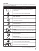
Safety Symbols This page depicts and describes safety symbols that may appear on this product. Read, understand, and follow all instructions on the machine before attempting to assemble and operate. Symbol Description READ THE OPERATOR’S MANUAL(S) Read, understand, and follow all instructions in the manual(s) before attempting to assemble and operate DANGER— ROTATING BLADES Never carry passengers. Never carry children, even with the blades off.
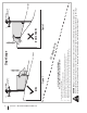
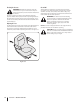
Section 2 — Important Safe Operation Practices Figure 1 line Figure 2 (TOO STEEP) 15° Slope WARNING! Slopes are a major factor related to tip-over and roll-over accidents which can result in severe injury or death. Do not operate machine on slopes in excess of 15 degrees. All slopes require extra caution. If you cannot back up the slope or if you feel uneasy on it, do not mow it. Always mow up and down slopes, never across the face of slopes. To check the slope, proceed as follows: 1.
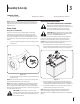
3 Assembly & Set-Up Contents of Crate • One Garden Tractor • One Operator’s Manual NOTE: This Operator’s Manual covers several models. Tractor features may vary by model. Not all features in this manual are applicable to all tractor models and the tractor depicted may differ from yours. CALIFORNIA PROPOSITION 65 WARNING! Battery posts, terminals, and related accessories contain lead and lead compounds, chemicals known to the State of California to cause cancer and reproductive harm.
Checking Tire Pressure Gas and Oil WARNING! Maximum tire pressure under any circumstances is 10 psi on rear tires and 12 psi on front tires. Equal tire pressure should be maintained at all times. The tires on your tractor may be over-inflated for shipping purposes. Reduce the tire pressure before operating the tractor. Recommended operating tire pressure is approximately 10 p.s.i. for the rear tires & 12 psi for the front tires. Check sidewall of tire for maximum psi.
4 Controls & Features Choke Control Hour Meter/Service Indicator Cruise Control/ Parking Brake Lever PTO/Blade Engage Lever Throttle Control Ignition Switch Module Forward Drive Pedal Brake Pedal Steering Tilt Lever Reverse Drive Pedal Electric Lift Switch Cup Holder Storage Compartment Fuel Cap Manual Lift Handle Cutting Height Lever Low Gas Window Hydrostatic Transmission Dipstick/Fill Tube Garden Tractor controls and features are illustrated in Fig 4-1 and described on the following pages.
Manual Lift Lever (If so equipped) LO 3 2 4 7 6 5 Forward Drive Pedal 8 9 HI The lift lever is located in the right fender and is used to raise and lower the deck. Pull the handle to the left out of the index notch and push downward to lower the deck, or pull upward to raise the deck. When the desired height is attained, move the lift handle to the right until fully in the index notch.
Low Gas Window The low gas window is located at the rear of the tractor. If the gas level is visible in this window, the tank should be re-filled. LCD FILL TANK IF GAS LEVEL IS SHOWN IN WINDOW Transmission Bypass Rod The transmission bypass rod is located at the rear of the tractor on the lower right section of the frame. When engaged, the rod opens a bypass within the hydrostatic transmissions, which allows the tractor to be pushed short distances by hand.
5 Operation WARNING! Avoid serious injury or death. Go up and down slopes, not across. Avoid sudden turns. Do not operate unit where it could slip or tip. If machine stops going uphill, stop PTO and back down the hill safely. Keep safety devices (guards, shields and switches) in place and working. Remove objects that could be thrown by the blades. Know location and function of all controls. Be sure the blades and the engine are stopped before placing hands or feet near blades.
Reverse Caution Mode Driving The Tractor WARNING! Avoid sudden starts, excessive speed and sudden stops. The REVERSE CAUTION MODE position of the key switch module allows the tractor to be operated in reverse with the blades (PTO) engaged. NOTE: Mowing in reverse is not recommended. WARNING! Use extreme caution while operating the tractor in the REVERSE CAUTION MODE . Always look down and behind before and while backing. Do not operate the tractor when children or others are around.
Driving On Slopes Setting The Cruise Control WARNING! Never engage the cruise control lever while traveling in reverse. Refer to the SLOPE GAUGE on page 8 to help determine slopes where you may operate the tractor safely. WARNING! Do not mow on inclines with a slope in excess of 15 degrees (a rise of approximately 2-1⁄2 feet every 10 feet). The tractor could overturn and cause serious injury. 1. Exercise extreme caution when changing direction on slopes.
Operating the Headlights The lamps are ON whenever the ignition key is rotated out of the STOP position. The lamps turn OFF when the ignition key is moved to the STOP position. Engaging the PTO Engaging the PTO transfers power to the cutting deck or other (separately available) attachments. To engage the PTO: 1. Move the throttle control lever to the FAST 2. Pull the PTO/Blade Engage lever position. See Figure 5-3. position.
6 Maintenance & Adjustments Maintenance Schedule Before Each use Check/Clean Engine Intake Screen Every 10 Hours Check Transmission Oil Every 200 Hours P Prior to Storing P P P Clean Hood/Dash Louvers Check Engine Oil Level Every 25 Hours P P P Change Transmission Oil & Filter * P Clean Battery Terminals P P Lube Front Axles and Rims Lube Pedal Pivot Points P P P * — For break-in operation, change after the first 50 hours of use and then every 200 hours thereafter.
4. While holding the free end of the oil drain hose over the oil collection container, unscrew the square head hose plug from the end of the hose. See Figure 6-1. Drain the engine oil into the collection container. Hydrostatic Transmission Oil Checking the Hydrostatic Transmission Oil The dipstick to check the hydrostatic transmission oil level is located on the back of the mower on the upper section of the frame. Refer to the Controls & Features section of this manual. 1.
3. Remove the drain plug and allow the transmission oil to drain into a clean container having a capacity of more than six quarts. Reinstall the drain plug. See Figure 6-3. Cleaning the Tractor Any fuel or oil spilled on the machine should be wiped off promptly. Do NOT allow debris to accumulate around the cooling fins of the engine, the transmission’s cooling fan or on any other part of the machine.
Steering Housing & Steering Shaft Parking Brake Adjustment The steering housing and steering shaft should be lubricated after every 25 hour of operation. To access the lube fittings, proceed as follows: If the tractor does not come to a complete stop when the brake pedal is completely depressed, or if the tractor’s rear wheels can roll with the parking brake applied (and the hydrostatic relief valve open), the brake is in need of adjustment. See your Cub Cadet dealer to have the brake adjusted. 1.
5. Loosen the jam nuts from the ball joints. See Figure 6-7. Pivot Bar Adjustment CAUTION: The tractor should be checked every 50 hours of operation for play between the frame channel and the pivot bar. Hex Lock Nut Check and adjust the pivot axle as follows: Ball Joint 1. Raise the front of the tractor and set it on jack stands, so the front wheels are suspended above the ground.
Lift Handle Adjustment (If so equipped) The effort required to operate the implement lift handle can be varied by loosening or tightening the lift assist spring adjusting bolt on the left side of the tractor. See Figure 6-9. Increase effort Decrease effort Adjustment Bolt Figure 6-9 NOTE: The deck and/or attachment should be installed before making adjustments to this spring. Place the deck/attachment into the lowest position for making adjustments. This ensures that the spring is extended the furthest.
7 Service Battery 3. Common Causes For Battery Failure Note which battery tray hole the RH side of the hold-down rod is hooked into. 4. Rotate the hold-down rod upward, over and around the battery to unhook from the battery tray. 5. Lift the battery out off the battery tray and remove from the tractor. 1. Overcharging 2. Undercharging 3. Loose and/or corroded connections 4. Excessive loads 6. Position the new battery and lower into the battery tray. 5. Freezing of electrolyte 7.
Headlights Refer to Replacement Parts section when replacement of head lamp bulbs is necessary. Replace headlight bulbs as follows: 1. Fully raise the hood of the tractor. 2. Unplug the wire harness leads from the headlight socket terminals. Note which wire connects to each terminal before disconnecting. 3. Rotate the socket assembly approximately 1⁄4 turn to align the socket tab with the reflector housing notch; then withdraw the bulb and socket assembly from the reflector housing. See Figure 7-3.
8 Troubleshooting Problem Excessive vibration Mower will not mulch grass (If equipped) Uneven cut 26 Cause Remedy 1. Cutting blade loose or unbalanced. 1. Tighten blade and spindle. 2. Damaged or bent cutting blade. 2. Replace blade. 1. Engine speed too low. 1. Place throttle in FAST (rabbit) position. 2. Wet grass. 2. Do not mulch when grass is wet. 3. Excessively high grass. 3. Mow once at a high cutting height, then mow again at desired height or make a narrower cutting swath. 4.
9 Replacement Parts Component Part Number and Description 925-1707D Battery 951-12725 Fuel Cap 946-04759A Choke Control Cable 946-04771A Throttle Control Cable 925-2054A Ignition Key 925-0963 12V Bulb Phone (800) 965-4CUB to order replacement parts or a complete Parts Manual (have your full model number and serial number ready). Parts Manual downloads are also available free of charge at www.cubcadet.com.
10 Attachments & Accessories GTX2100 The following attachments and accessories are compatible for Cub Cadet GTX2100. See your Cub Cadet dealer or the retailer from which you purchased your tractor for information regarding price and availability. Model Number 28 Description GT2000 & GTX2000 The following attachments and accessories are compatible for Cub Cadet GT2000. See your Cub Cadet dealer or the retailer from which you purchased your tractor for information regarding price and availability.
Notes 11 29
FEDERAL and/or CALIFORNIA EMISSION CONTROL WARRANTY STATEMENT YOUR WARRANTY RIGHTS AND OBLIGATIONS MTD Consumer Group Inc, the United States Environmental Protection Agency (EPA), and, for those products certified for sale in the state of California, the California Air Resources Board (CARB) are pleased to explain the emission (evaporative and/or exhaust) control system (ECS) warranty on your outdoor 2006 and later small off-road spark-ignited engine and equipment (outdoor equipment engine) In California, n
10. Add-on or modified parts that are not exempted by the Air Resources Board may not be used. The use of any non-exempted add-on or modified parts by the ultimate purchaser will be grounds for disallowing a warranty claims. MTD Consumer Group Inc will not be liable to warrant failures of warranted parts caused by the use of a non-exempted add-on or modified part.
CUB CADET LLC MANUFACTURER’S LIMITED WARRANTY FOR SERIES 2000 TRACTORS IMPORTANT: To obtain warranty coverage owner must present an original proof of purchase and applicable maintenance records to the servicing dealer. Please see the operator’s manual for information on required maintenance and service intervals. In the U.S.A. Check your Yellow Pages, or contact Cub Cadet LLC at P.O. Box 361131, Cleveland, Ohio 44136-0019, call 1-877-282- 8684 or log on to our website at www.cubcadet.com.