Operator’s Manual Triple Rear Bagger — 19A70040100 WARNING READ AND FOLLOW ALL SAFETY RULES AND INSTRUCTIONS IN THIS MANUAL BEFORE ATTEMPTING TO OPERATE THIS MACHINE. FAILURE TO COMPLY WITH THESE INSTRUCTIONS MAY RESULT IN PERSONAL INJURY. CUB CADET LLC, P.O. BOX 361131 CLEVELAND, OHIO 44136-0019 Printed In USA Form No.
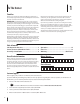
1 To The Owner Thank You Thank you for purchasing a Cub Cadet Bagging attachment. It was carefully engineered to provide excellent performance when properly operated and maintained. IMPORTANT: If installing this bagging kit on a ZF-L (lap bar) unit, bumper adaptor kit 19A70046100 is required and must be installed prior to attempting to install this bagger. See the retailer in which you purchased this bagger to purchase this adapter kit. Please read this entire manual prior to operating the equipment.
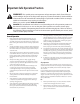
Important Safe Operation Practices 2 WARNING! This symbol points out important safety instructions which, if not followed, could endanger the personal safety and/or property of yourself and others. Read and follow all instructions in this manual before attempting to operate this machine. Failure to comply with these instructions may result in personal injury. When you see this symbol. HEED ITS WARNING! DANGER! This attachment was built to be used according to the safe operation practices in this manual.
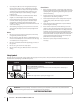
3. Use slow speed. Choose a low enough speed setting so that you will not have to stop or shift while on the slope. Tires may lose traction on slopes even though the brakes are functioning properly. Always keep machine in gear when going down slopes to take advantage of engine braking action. 4. Follow the manufacturer’s recommendations for wheel weights or counterweights to improve stability. 5. Keep all movement on the slopes slow and gradual. Do not make sudden changes in speed or direction.
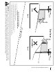
(OK) Figure 1 line Slope Gauge 10° Slope 1 0 ° d a s hed USE THIS SLOPE GAUGE TO DETERMINE IF A SLOPE IS TOO STEEP FOR SAFE OPERATION! To check the slope, proceed as follows: 1. Remove this page and fold along the dashed line. 2. Locate a vertical object on or behind the slope (e.g. a pole, building, fence, tree, etc.) 3. Align either side of the slope gauge with the object (See Figure 1 and Figure 2 ). 4. Adjust gauge up or down until the left corner touches the slope (See Figure 1 and Figure 2). 5.
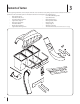
Contents of Carton 3 Before beginning installation, remove all parts from the carton to make sure everything is present. Carton contents are listed and shown below. Three hardware packs are included in this kit and are detailed on the following page. • Lower Chute Discharge Plate • Grass Catcher Cover • Upper Chute Tube • Hitch Bracket Kit (3 Pcs.
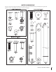
CONTENTS OF HARDWARE PACK This grass collector kit is shipped with three loose hardware packs enclosed. Please check your hardware packs against the illustrations below. The quantities for each item is listed in parenthesis.
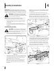
4 Assembly & Installation IMPORTANT: If installing this bagging kit on a ZF-L (lap bar) unit, bumper adaptor kit 19A70046100 is required and must be installed prior to attempting to install this bagger. See the retailer in which you purchased this bagger to purchase this adapter kit. CAUTION: Do not attempt to install this bagging Note: The 712-3010 hex nuts should be tightened (against bumper if bolts are inside-out, or against bracket if bolts are outside-in). 3.
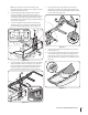
Note: If you decided to leave the hitch support only finger tight during the assembly process, tighten all of the hardware securely at this time. 6. 7. 9. Install the bagger upright mounting bracket onto the mounting assembly (1 in Figure 4-4) of the tractor by hooking it over the bagger cross-support bracket near the center, lining up the corresponding mounting hole with the deck size of the tractor this bagger is being installed on. See the inset of Figure 4-4.
12. Clip in the other side by flexing the screen and pushing it down into the provided cutout hole. See Figure 4-8. Make sure screen sits under the cover’s lip Figure 4-8 13. Cover mounts in between these two tabs Figure 4-11 Figure 4-9 14. 10 Figure 4-10 Install the bagger cover onto the bag support assembly, as seen in Figure 4-9. The plastic cover goes inside of the two mounting tabs. Slide the hinge pin into the hole located on the mounting tab, as in Figure 4-10.
15. Open the bagger cover by pushing in on the rear, right-side tab with your right hand, as seen in 1 of Figure 4-12, and lifting the cover with your left hand in the center rear of the bagger cover, 2. Installing the Deck Baffle Note: Installing the deck baffle may be easiest with the deck removed as instructed in the tractor’s operator’s manual, however it is not mandatory.
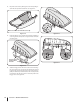
Assembling the Discharge Chute Components 1. Insert the inner boot bracket into the chute elbow as shown in Figure 4-15. 2. Install the discharge chute top mounting bracket onto the topside of the discharge chute using five (5) 710-0751 hex bolts, as shown in Figure 4-15, and securing with three (3) 736-0270 bevel washers and five (5) 712-3027 flange lock nuts, all included in hardware pack 689-00337.
6. Attach the retainer strap on the discharge chute to the retainer clip on the deck. See Figure 4-20. 7. Install the chute adapter onto the chute elbow by lining up the tabs and sliding the adapter over the chute elbow, as shown in Figure 4-21. Secure the chute adapter by installing two 710-3013 hex screws into the holes shown and secure with two 712-0442 cap lock nuts, included in hardware pack 689-00337. Flange Figure 4-18 Installing the Discharge Chute On The Tractor 1.
8. Install the upper chute tube over the chute tube extension, as shown in Figure 4-22. Figure 4-22 9. Secure the upper chute tube to the lower discharge chute by stretching the rubber strap on the upper chute tube downward and hooking it onto the pin on the lower chute tube. See Figure 4-23. Figure 4-23 10. 14 With the bagger cover open, install the upper chute over the chute adapter, and rest the top so that the chute support sits in the upper chute groove. See Figure 4-24.
5 Operation Bagger Usage 3. NOTE: When all of the grass bags are full, place the tractor on a firm, level surface, disengage the PTO, turn the tractor engine off and set the parking brake. 1. Pivot the seat forward and up. 2. Lift up grass bag cover by pushing in on the rear, right-side tab with your right hand, as seen in 1 of Figure 5-1, and lifting the cover with your left hand in the center rear of the bagger cover, 2. Do not remove the chute tube assembly from the tractor.
19A70040100 Parts List 26 14 41 3 6 5 43 10 30 29 42 12 4 1 19 15 36 1 31 4 2 1 13 34 37 35 8 38 33 27 32 16 33 28 35 18 17 20 39 25 21 7 40 9 11 40 24 16 23 22 1
Ref. Part Number Description 1. 912-3027 Hex Flange Nut, 1/4-20 2. 736-0270 Bevel Washer, .265 x .750 x .060 3. 912-0442 Cap Lock Nut, 1/4-20 4. 710-0751 Hex Head Screw, 1/4-20 x .620 5. 710-3013 Hex Head Screw, 1/4-20 x .50 6. 736-3092 Flat Washer, .265 x 1.0 x .030 7. 712-04064 Flange Lock Nut, 1/4-20 8. 603-05167 Bagger Bracket Assembly 9. 723-04009A Chute Strap, 11.65" Lg. 10. 911-04069 Grass Catcher Pin, 1/4-20 11. 710-0924 Machine Screw, 1/4-20 x 0.750 12.
Notes 18 7
Section 7 — Notes 19
CUB CADET LLC MANUFACTURER’S LIMITED WARRANTY FOR SEPARATELY SOLD ATTACHMENTS AND ACCESSORIES IMPORTANT: To obtain warranty coverage owner may be required to present an original proof of purchase and applicable maintenance records to the servicing dealer. Please see the operator’s manual for information on required maintenance and service intervals.