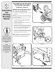
To The Owner • Carton Contents • Assembly • Parts Lists • Warranty OPERATOR’S MANUAL Twin Rear Bagger Kit For i1000 Series Lawn Tractors with a 42” Timed Deck Model 19A70001000 IMPORTANT READ SAFETY RULES AND INSTRUCTIONS CAREFULLY BEFORE OPERATION PRINTED IN U.S.A. CUB CADET LLC, P.O. BOX 361131 CLEVELAND, OHIO 44136-0019 FORM NO.
This Operator’s Manual is an important part of your new grass collector. It will help you assemble, prepare and maintain the unit for best performance. Please read and understand what it says. Finding and Recording Model Number BEFORE YOU START ASSEMBLING YOUR NEW EQUIPMENT, please locate the model plate and copy the information from it in this Operator’s Manual for future reference.
NOTES Use this page to make notes and write down important information.
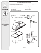
2 Carton Contents CONTENTS OF CARTON Before beginning installation, remove all parts from the carton to make sure everything is present. Carton contents are listed below and shown in Figure 2-1.
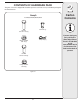
CONTENTS OF HARDWARE PACK This grass collector kit is shipped with a hardware pack enclosed. Please check your hardware pack against the illustration below. Group A Assembling and Attaching Mounting Bracket 2 Carton Contents Clevis Pin (1) Hex Bolt 5/16-18 x .750 (6) Hairpin Clip (1) Flange Lock Nut 5/16-18 (6) Hex Bolt 1/4-20 x .620 (8) Flange Lock Nut 1/4-20 (8) Figure 2-2 5 If you are missing any parts, call the Customer Dealer Referral Line at 1-877-282-8684, or visit www.cubcadet.
3 Assembling and Attaching Mounting Bracket Assembling and Attaching The Bracket Assembly (Hardware Group A) IMPORTANT: Before assembly, place the tractor on a firm, level surface, disengage the PTO, stop the tractor engine and set the parking brake. 1. Assemble the mounting bracket assembly as shown in Figure 3-1. NOTE: The mounting bracket assembly may have been preassembled at the factory, if this is the case, skip Step 1 and proceed to Step 2. 2.
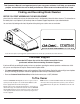
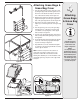
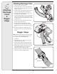
Attaching Grass Bags & Grass Bag Cover 1. Place the support tube in position on the rear of unit by sliding the support tube down through the holes in the left side of the bracket assembly. Use the inside hole on the bracket assembly. Refer to Figure 4-1. 2. Attach the grass bags by hooking them onto the grass bag bracket using the slots in the grass bag and the tabs on the grass bag bracket as shown in Figure 4-2. 3.
5 Attaching Discharge Chute & Bagger Usage Attaching Discharge Chute A 1. Lower the deck to its lowest position. 2. Raise the chute deflector on the deck (A) and hold it while you position the discharge chute over the chute opening. See Fig. 5-1. B 3. Insert the pin (B) on the discharge chute into the hole on the deck as indicated by the arrow in Fig. 5-1. 4. Push down on the discharge chute so that it covers the opening of the deck completely. C 5.
6 NOTES Use this page to take notes and write down important information.
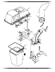
4 18 11 12 2 16 14 19 17 12 14 8 21 17 20 13 1 7 30 14 9 32 20 14 20 7 28 29 26 17 27 13 31 24 14 25 13 10 23 22 9 6 3 15 10
PART NUMBER 8 DESCRIPTION 1 16587D Bracket Support 2 16592 Support Tube Assembly 3 764-0221 Catcher Bag 4 664-04017 Grass catcher Cover Assembly 5 683-04348 Mounting Bracket - RH 6 683-04350 Mounting Bracket - LH 7 710-0597 Screw 1/4-20 x 1” 8 710-0751 Hex Screw 1/4-20 x0.620 9 710-3008 Hex Screw 5/16-18 x 0.
CUB CADET LLC MANUFACTURER’S LIMITED WARRANTY FOR SEPARATELY SOLD ATTACHMENTS AND ACCESSORIES IMPORTANT: To obtain warranty coverage owner may be required to present an original proof of purchase and applicable maintenance records to the servicing dealer. Please see the operator’s manual for information on required maintenance and service intervals. a.