Operator’s Manual Triple Rear Bagger — 19A40002100 WARNING READ AND FOLLOW ALL SAFETY RULES AND INSTRUCTIONS IN THIS MANUAL BEFORE ATTEMPTING TO OPERATE THIS MACHINE. FAILURE TO COMPLY WITH THESE INSTRUCTIONS MAY RESULT IN PERSONAL INJURY. CUB CADET LLC, P.O. BOX 361131 CLEVELAND, OHIO 44136-0019 Printed In USA Form No.
1 To The Owner Thank You Thank you for purchasing a bagging attachment manufactured by Cub Cadet. It was carefully engineered to provide excellent performance when properly operated and maintained. Please read this entire manual prior to operating the equipment. It instructs you how to safely and easily set up, operate and maintain your equipment. Please be sure that you, and any other persons who will operate the machine, carefully follow the recommended safety practices at all times.
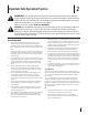
Important Safe Operation Practices 2 WARNING! This symbol points out important safety instructions which, if not followed, could endanger the personal safety and/or property of yourself and others. Read and follow all instructions in this manual before attempting to operate this machine. Failure to comply with these instructions may result in personal injury. When you see this symbol. HEED ITS WARNING! DANGER! This attachment was built to be used according to the safe operation practices in this manual.
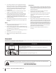
3. Use slow speed. Choose a low enough speed setting so that you will not have to stop or shift while on the slope. Tires may lose traction on slopes even though the brakes are functioning properly. Always keep machine in gear when going down slopes to take advantage of engine braking action. 4. Follow the manufacturer’s recommendations for wheel weights or counterweights to improve stability. 5. Keep all movement on the slopes slow and gradual. Do not make sudden changes in speed or direction.
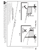
(OK) Figure 1 line Slope Gauge 10° Slope 1 0 ° d a s hed USE THIS SLOPE GAUGE TO DETERMINE IF A SLOPE IS TOO STEEP FOR SAFE OPERATION! To check the slope, proceed as follows: 1. Remove this page and fold along the dashed line. 2. Locate a vertical object on or behind the slope (e.g. a pole, building, fence, tree, etc.) 3. Align either side of the slope gauge with the object (See Figure 1 and Figure 2 ). 4. Adjust gauge up or down until the left corner touches the slope (See Figure 1 and Figure 2). 5.
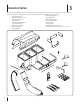
3 Contents of Carton Before beginning installation, remove all parts from the carton to make sure everything is present. Carton contents are listed below and shown in Figure 3-1. Two hardware packs are included in this kit and are detailed on the following page. • Chute Discharge Plate • Grass Catcher Cover • Upper Chute Tube • Grass Catcher Cover Screen • Chute Tube Extension • Hitch Bracket Kit (3 Pcs.
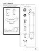
CONTENTS OF HARDWARE PACK This grass collector kit is shipped with two loose hardware packs enclosed. Please check your hardware packs against the illustrations below. The quantities for each item is listed in parenthesis.
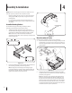
4 Assembly & Installation NOTE: References to left, right, front and rear of the tractor are from the operator’s position, unless otherwise stated. • Before assembly, place the tractor on a firm, level surface, disengage the PTO, stop the tractor engine and set the parking brake. • For convenience, pivot the seat forward and leave it in that position until the grass collector is fully mounted and assembled.
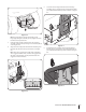
5. Secure the vertical support bracket to the mounting assembly using a carriage bolt (710-0276) and wing knob (720-04122) from hardware pack 689-00328A. See Figure 4-7. Align hole on bracket with hole on tractor Figure 4-5 Note: If you decided to leave the hitch support only finger tight during the assembly process, tighten all of the hardware securely at this time. 3.
Assembling Remaining Bagger Components 4. Now that the mounting brackets are assembled and are in place on the tractor, follow these steps to assemble the remaining bagger components. 1. Clip in the other side by flexing the screen and pushing it down into the provided cutout hole. See Figure 4-11.
7. Open Hood by pushing in on the rear, right-side tab with your right hand, as seen in 1 of Figure 4-15, and lifting the cover with your left hand in the center rear of the bagger cover, 2. 2 1 Figure 4-13 Figure 4-15 8. Install the bag assemblies onto the bag support brackets by inserting the front edge in first, as seen in Figure 4-16, and setting the back edge down until it fits into the assembly.
Attaching Blades 6. WARNING! Always protect your hands while servicing blades by wearing heavy work gloves or using heavy rags. NOTE: High-lift bagging blades are included in the grass-catcher kit. Replace the blades with these new blades and save the existing blades as replacements or to reinstall on the blade spindles when not using the bagger kit.
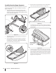
Installing the Chute Discharge Plate 1. Remove the discharge chute by removing the two flange lock nuts securing it. 2. With a hammer, lightly tap the bolts out. Discard the bolts and flange lock nuts. 3. Install the chute discharge plate to the bottom side of the deck opening, as seen in Figure 4-19, using two carriage bolts supplied in hardware pack 689-00163. 2. Install the new chute stop bracket, from the loose parts, at the same position on the deck. See the right Inset of Figure 4-20.
6. NOTE: Check the upper chute for a cardboard insert installed for shipping purposes. If the insert is present, remove it before continuing with Step 8. Attach the retainer strap on the discharge chute to the retainer clip on the deck. Refer to Figure 4-23. Note: For the chute elbow to be properly installed, the bottom edge must fall below the bottom of the deck opening and the tab on top of the elbow should rest above the deck opening. 8.
5 Operation Bagger Usage 3. NOTE: When all of the grass bags are full, place the tractor on a firm, level surface, disengage the PTO, turn the tractor engine off and set the parking brake. 1. Pivot the seat forward and up. 2. Lift up grass bag cover by pushing in on the rear, right-side tab with your right hand, as seen in 1 of Figure 5-1, and lifting the cover with your left hand in the center rear of the bagger cover, 2. Do not remove the chute tube assembly from the tractor.
19A40002100 Parts List 2 12 19 22 8 4 20 21 13 32 11 18 17 6 5 9 10 3 16 7 5 24 5 27 6 6 15 30 23 34 6 25 24 28 26 31 22 21 23 29 1 16 14
Ref. Part Number Description 1. 931-04291 Upper Chute Assembly 2. 931-04298 Triple Bagger Cover Assembly 3. 731-06497 Upper Chute Support 4. 731-06504 Bagger Cover Screen 5. 710-0276 Carriage Screw, 5/16-18 x 1.00” 6. 720-04122 Wing Knob, 5/16-18 7. 711-0309A Clevis Pin, .62” Dia. 8. 964-04090A Grass-bag Assembly 9. 683-04498A-0637 Triple Bag Support Assembly 10. 683-04519A-0637 Vertical Support Bracket 11. 711-05079 Cover Hinge Pin 12.
Notes 18 7
Section 7 — Notes 19
CUB CADET LLC MANUFACTURER’S LIMITED WARRANTY FOR SEPARATELY SOLD ATTACHMENTS AND ACCESSORIES IMPORTANT: To obtain warranty coverage owner may be required to present an original proof of purchase and applicable maintenance records to the servicing dealer. Please see the operator’s manual for information on required maintenance and service intervals.