Safe Operation Practices • Set-Up • Operation • Maintenance • Service • Troubleshooting • Warranty Operator’s Manual Series 2500 Garden Tractor - Model GT 2544 WARNING READ AND FOLLOW ALL SAFETY RULES AND INSTRUCTIONS IN THIS MANUAL BEFORE ATTEMPTING TO OPERATE THIS MACHINE. FAILURE TO COMPLY WITH THESE INSTRUCTIONS MAY RESULT IN PERSONAL INJURY. CUB CADET LLC, P.O. BOX 361131 CLEVELAND, OHIO 44136-0019 Printed In USA Form No.
Thank You not be applicable to all models. Cub Cadet LLC reserves the right to change product specifications, designs and equipment without notice and without incurring obligation. Thank you for purchasing a Garden Tractor manufactured by Cub Cadet LLC. It was carefully engineered to provide excellent performance when properly operated and maintained. This product has met the rigid safety standards of the Outdoor Power Equipment Institute and an independent testing laboratory.
Section 1: Important Safe Operation Practices WARNING: This symbol points out important safety instructions which, if not followed, could endanger the personal safety and/or property of yourself and others. Read and follow all instructions in this manual before attempting to operate this machine. Failure to comply with these instructions may result in personal injury. When you see this symbol.
c. When practical, remove gas-powered equipment from the truck or trailer and refuel it on the ground. If this is not possible, then refuel such equipment on a trailer with a portable container, rather than from a gasoline dispenser nozzle. 7. Plan your mowing pattern to avoid discharge of material toward roads, sidewalks, bystanders and the like. Also, avoid discharging material against a wall or obstruction which may cause discharged material to ricochet back toward the operator. d.
25. 26. 27. 28. 29. Do Not: Disengage all attachment clutches, depress the brake pedal completely and shift into neutral before attempting to start engine. Your machine is designed to cut normal residential grass of a height no more than 10”. Do not attempt to mow through unusually tall, dry grass (e.g., pasture) or piles of dry leaves. Dry grass or leaves may contact the engine exhaust and/or build up on the mower deck presenting a potential fire hazard.
5. 6. Notice Regarding Emissions Check the blade(s) and engine mounting bolts at frequent intervals for proper tightness. Also, visually inspect blade(s) for damage (e.g., excessive wear, bent, cracked). Replace the blade(s) with the original equipment manufacturer’s (O.E.M.) blade(s) only, listed in this manual.
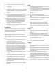
d o t t e d lin 15° s l o p e) or a fence post repr e s e n ts a e( or a corner of a building... ng Fold a lo Sight and hold this level with a vertical tree... 15° Use this page as a guide to determine slopes where you may not operate safely. WARNING: Do not operate your lawn mower on such slopes. Do not mow on inclines with a slope in excess of 15 degrees (a rise of approximately 2-1/2 feet every 10 feet). A riding mower could overturn and cause serious injury.
Section 2: Assembly & Set-Up TRACTOR STEERING WHEEL For shipping purposes, the steering wheel was removed from the steering shaft. Pivot the seat rearward and remove any packaging material from the seat. Cut the ties securing the steering wheel and remove any packaging material. Install the steering wheel as follows: CONNECT THE BATTERY WARNING: Battery posts, terminals and related accessories contain lead and lead compounds. Wash hands after handling.
Section 3: Controls & Features B C A H E I F D M G J K L O Q Q N P A. B. C. D. E. F. G. H. I. Hour Meter/Battery Display Indicator Panel/Hour Meter Key Switch Module Power Take-Off (PTO) Control Switch Throttle Control Lever Choke Control Parking Brake/Cruise Lever Brake Pedal Forward Control Pedal J. K. L. M. N. O. P. Q.
A. HOUR METER/BATTERY DISPLAY The hour meter records and digitally displays the hours that the tractor has been operated (tenths of an hour-right most digit). NOTE: The oil pressure indicator may illuminate when the key switch is turned to an on position, but should turn off when the engine is started. PTO Engaged Indicator (Refer to Figure 3-2) • This indicator illuminates when the key switch is turned to the "Start" position while the PTO switch is in the "Engaged" position.
WARNING: To prevent accidental starting and/or battery discharge, remove the key from the key switch when the tractor is not in use. To engage the cruise control, depress the forward control pedal to attain your desired speed; then push the parking brake/cruise control lever downward. While holding the lever down, release pressure from the drive pedal. This will engage the cruise control and allow the tractor to remain at approximately that same speed while removing your foot from the forward drive pedal.
L. LIFT HANDLE The lift handle is located in the left fender and is used to raise and lower equipment used with the tractor. The equipment can be set in any of six positions by depressing the top button on the handle, moving the handle to the desired position, then releasing the button. It may be necessary to push or pull slightly on the handle to depress the button. A lift assist spring reduces the effort needed to lift attachments. To adjust assist spring tension refer to “Maintenance & Adjustments”.
Section 4: Operation WARNING: Before you operate the tractor, study this manual carefully. Familiarize yourself with the operations of all the instruments and controls. Learn to operate this machine safely. Don’t risk INJURY or DEATH. NOTE: Purchase gasoline in small quantities. Do not use gasoline left over from the previous season, to minimize gum deposits in the fuel system. Gasohol (up to 10% ethyl alcohol, 90% unleaded gasoline by volume) is an approved fuel.
STARTING THE ENGINE WARNING: For personal safety, the operator must be sitting in the tractor seat when starting the engine. Never try to start the engine while standing on the ground. 2. Disengage all possible external loads. 3. Be sure the battery is in good condition. A warm battery has much more starting capacity than a cold battery. 4. Use fresh winter grade fuel. Winter grade gasoline has higher volatility to improve starting. Do not use gasoline left over from summer. 5.
DRIVING THE TRACTOR NOTE: Avoid sudden starts, excessive speed and sudden stops. • WARNING: Do not leave the seat of the tractor without disengaging the PTO and engaging the parking brake. If leaving the tractor unattended, turn the ignition key off and remove the key. DRIVING ON SLOPES Refer to the SLOPE GAUGE on page 7 to help determine slopes where you may not operate safely. WARNING: Do not mow on inclines with a slope in excess of 15 degrees (a rise of approximately 2-1/2 feet every 10 feet).
• Turn the ignition switch to “STOP’” and remove the key from the switch before dismounting. HITCH HOLE PTO CLUTCH BREAK-IN (Before initial use ONLY) Before operating the new clutch under load (mowing grass, etc.), perform the following break-in procedure: 1. Start and run the engine a few minutes to warm up. 2. With the mowing deck installed and the engine running at approximately 50% throttle, engage and disengage the clutch at ten second intervals (ten seconds ON - ten seconds OFF) five times.
IMPORTANT: The operator MUST be seated in the tractor seat. CHUTE DEFLECTOR CHUTE DEFLECTOR HINGE ROD 1. Start the engine and engage the PTO as previously instructed in this Operator’s Manual. 2. Turn the key from the “NORMAL MOWING” (Green) position to the “REVERSE CAUTION MODE” (Yellow) position of the key switch module. Refer to Figure 4-4. HOOKS RETAINING LIP (ON BACKSIDE OF PLUG) 3. Depress the “REVERSE PUSH BUTTON” (Orange/Triangular Button) at the top/right corner of the key switch module.
MOWING WARNING: To avoid possible injury, do not allow anyone in the area opposite the discharge chute while mowing. Although the area has been supposedly cleared of foreign objects, small objects may be picked up and discharged by the mower. Never direct the discharge of material toward bystanders or allow anyone near the machine while in operation. IMPORTANT: Do not engage the mower deck when lowered in grass. Premature wear and possible failure of the ‘V” belts and PTO clutch will result.
Section 5: Maintenance and Adjustments MAINTENANCE 2. Clean the area around the oil fill plug/dipstick to prevent debris from entering the transmission case. 3. Remove the oil fill plug/dipstick from the oil fill port and SLOWLY pour oil into the oil fill port. Fill the transmission case until the oil level reaches the “FULL” mark on the dipstick (Refer to Figure 5-1). 4. Reinstall the oil fill plug/dipstick securely into the oil fill port.
1. Spray the terminals and exposed wire with a battery terminal sealer, or coat the terminals with a thin coat of grease or petroleum jelly, to protect against corrosion. • Near the front of the steering housing, locate the lube fitting for the segment gear shaft. Apply lubrication through the lube fitting, using a pressure lubricating gun. 2. Always keep the battery cables and terminals clean and free of corrosion.
• Move the tractor to an area within reach of the hose where the dispersal of wet grass clippings is not objectionable to you. Disengage the PTO, engage the parking brake, and stop the engine. • Pull back the lock collar of the nozzle adapter and push the adapter onto one of the deck wash nozzles at either end of the mower deck. Release the lock collar to lock the adapter on the nozzle. See Figure 5-2.
NOTE: We do not recommend the use of a pressure washer or garden hose to clean your tractor. They may cause damage to electrical components; spindles; pulleys; bearings; or the engine. The use of water will result in shortened life and reduce serviceability. ADJUSTING LIFT ASSIST SPRING TENSION The effort required to operate the implement lift handle can be varied by loosening or tightening the lift assist spring adjusting bolts on each side of the tractor (See Figure 5-4).
• NOTE: Check the tires for proper inflation before making a leveling adjustment. To level the deck, the tractor and deck MUST be placed on a hard, level surface during adjustment. adjustment ferrule and right hand lift link rod (Refer to Figure 5-7). 7. Loosen the upper jam nut on the lift link rod and turn away from the adjustment ferrule. Turn the lower lock nut upward (tighten) on the threads of the rod to raise the right side of the mower deck.
3. Refer to Figure 5-9. Measure and record the distance from the front cutting edge to the ground (measurement A), and from the rear cutting edge to the ground (measurement B), for each of the blades. The front edge of each blade (measurement A) should be lower than its back edge (measurement B) by 1/8 to 1/4 inch.
e. Note the index hole position used for the rear gauge wheels. Insert a shoulder screw into a front ball wheel and slide a bell washer onto the threads of the shoulder bolt. Note: The crown (rounded side) of the bell washer should be against the shoulder of the bolt. Install the shoulder bolt and wheel in the corresponding index hole of the front gauge wheel bracket. Repeat to install the other front ball wheel. CUTTING HEIGHT ADJUSTMENT The mower can be set in multiple positions.
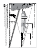
10 — 6 CHECK OIL — 2 LEVEL BEFORE EACH USE 12 — 50 50 10 — 7 — 13 10 — 4 50 — 11 100 — 14 50 10 — 6 10 — 6 10 — 8 10 — 5 25 — 10 — 12 25 — 10 1— BOTH SIDES 25 — 9 BOTH SIDES 10 — 3 LEFT SIDE 100 — 15 CHECK OIL LEVEL BEFORE EACH USE LUBRICATION GUIDE
LUBRICATION TABLE Check at Hours Change at Hours Capacity Engine crankcase Check before each use 100 Approx. 4 pints Hydro transmission and transaxle with filter Check before each use Add as needed Approx. 6 qts Point of Lubrication Anticipated Air Temperature Above + 32°F Below + 32°F Cub Cadet Engine Oil SAE 10W30 Cub Cadet Engine Oil SAE 5W20 or 5W30 Cub Cadet Drive System Fluid Plus NOTE: Cub Cadet Drive System Fluid Plus is specially formulated for this application.
MAINTENANCE CHART Operation to be performed Before each use Check engine oil level X Fill fuel tank X 10 hours or once a month Change engine oil & oil filter Every 25 hours 50 hours or twice a season After first 25 hours, engine oil only Check transmission oil level 100 hours or yearly Before storage every 100 hours X X Replace transmission oil filter After first 10 hours X After first 50 hours X Clean & re-oil foam air precleaner Every 100 hours thereafter X X Check battery terminals
Section 6: Service This section contains information for the various adjustments and service procedures on the tractor. Refer to the Kohler engine manual for engine service instructions and intervals, but use the instruction in the following sub-section when the draining the engine crankcase. 7. Clean the drain valve and push the plastic dust cap onto the valve. OIL FILTER DRAINING THE ENGINE OIL OIL DRAIN VALVE NOTE: The engine oil should be changed after the first 25 hours of operation.
having a capacity of more than 6 quarts. Reinstall the drain plug (See Figure 6-2). 1. Engage the brake pedal lock. If the tractor can be pushed forward or rearward, the braking force must be increased. 2. Release the brake pedal lock. If the tractor cannot be pushed forward or rearward, the braking force must be decreased. IMPORTANT: If the transmission oil is to be re-used, cover the container holding the drained oil to prevent contamination.
WHEEL ALIGNMENT The front wheels should toe-in approximately 1/8 to 1/4 inch, as measured across dimensions A and B shown in Figure 6-4. 4. Loosen the jam nuts from the ball joints (See Figure 6-5). 5. Disconnect the front ball joints from the steering arms by removing the hex lock nuts (Refer to Figure 6-5). Manually move each wheel to achieve the required toe-in and equal D measurements.
2. Raise the rear of the tractor, so that the rear tires are at least one inch above the surface, and set it on jack stands. Make certain the jack stands are positioned to balance the tractor and prevent tipping. PIVOT AXLE ADJUSTMENT BOLTS WARNING: The operator presence safety circuit will stop the engine if the seat is empty when the brake pedal is released. If an assistant is seated when adjusting the neutral setting, use extreme caution to prevent the tractor from tipping or rolling.
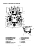
3 10 2 4 5 1 CONTROL CAM 6 7 9 1. 2. 3. 4. 5. 6. 7. 8. 9. 10. Front Control Rod Rear Control Rod Hex Tap Screw Hex Wash Hd Tapp Screw Control Arm Control Arm Pin Neutral Arm Centering Pin Neutral Return Adjust. Brkt.
2. Unplug the wire harness leads from the headlight socket terminals. Note which wire connects to each terminal before disconnecting. 3. Rotate the socket assembly approximately 1/4 turn to align the socket tab with the reflector housing notch; then withdraw the bulb and socket assembly from the reflector housing. 4. Push the bulb inward and turn counterclockwise to remove from the socket. HOLDDOWN ROD ROTATE UPWARD HEX SCREW SOCKET TAB BATTERY TRAY TERMINAL REFLECTOR NOTCH Figure 6-8 6.
REMOVAL OF MOWER DECK WARNING: Before removing the mower deck, place the PTO switch in the “OFF” position, engage the parking brake, turn the ignition key to the “OFF” position and remove the key from the switch. Disconnect the spark plug wire for additional safety. WARNING: The exhaust system is HOT. To avoid personal injury, allow the engine and exhaust system to cool before proceeding with the following PTO belt removal instructions. 4. Open the tractor hood.
6. Pull the deck support pins outward, turn downward and release so both spring-loaded pins are held in the disengaged position against the outer surface of the deck brackets (Refer to Figure 6-14).
When removing the blades, use a 1-1/8 inch wrench to hold the hex head of the spindle bolt when loosening the hex nut securing the blade. A block of wood may be placed between the deck housing and the cutting edge of the blade to help in breaking loose the hex nut securing the blade (Refer to Figure 6-17). 4. Pull the movable flat idler pulley away from the backside of the belt and slip the belt under the idler pulley. 5. Remove the old drive belt from the spindle pulleys and flat idler pulley. 6.
SLOT IN REAR DECK BRACKETS (BOTH SIDES) FRONT ROLLER BRACKET IMPLEMENT LIFT LINKS (BOTH SIDES) FRONT LIFT ROD Figure 6-19 4. Refer to Figure 6-20 to ensure the correct orientation of the front lift rod/bracket assembly [form (bend) in sides of rod point downward]. From the front of the tractor, push downward and hold the tractor quick-attach rod. Slide the shoulder bolts on each side of the front lift rod/bracket assembly fully into the left and right tractor latch receivers.
8. Pull both deck support pins outward and rotate rearward to disengage the outer surface to the rear deck brackets. Release the pins, making certain each deck support pin passes through the inner hole of the rear deck bracket. The spring tension will push the pins inward and, if aligned, through the hole in each implement lift link (See Figure 6-23). LIFT LINK HOLE (BOTH SIDES) 10. Open the tractor hood.
14. Working from the left/rear of the mower deck, make sure there is only a 1/4 twist inward in both runs of the belt. Then install the the narrow side of the rearward end of the PTO belt onto the upper pulley of the deck center double-pulley (Refer to Figure 6-27). 15. While holding the belt in position, rotate and engage the deck idler arm lever into its stop bracket to tension the PTO belt (See Figure 6-28). LEVER STOP BRACKET PTO BELT IDLER ARM LEVER Figure 6-28 FRONT OF DECK 16.
Section 7: Trouble Shooting Possible Cause Possible Remedy HARD TO START No gasoline in fuel tank or carburetor ..................... Fill the tank with gasoline. Check the fuel line, carburetor and fuel filter. Fuel line or carburetor clogged ............................... Clean the fuel line and carburetor with a commercial carburetor cleaner. Fuel filter plugged ................................................... Replace. Water in gasoline ....................................................
Trouble Shooting Possible Cause Possible Remedy LACK OF POWER Air cleaner clogged ................................................. Service the air cleaner element. Refer to “MAINTENANCE.” Engine overload ...................................................... Reduce the load. Engine overheated .................................................. Make sure the air intake screen, shrouding, and engine cooling fins are free of accumulated dirt and debris. Refer to “MAINTENANCE.
Section 8: Replacement Parts MODEL GT 2544 ENGINE OIL SERIES 2500 22 HP KOHLER Engine Oil Requirements approx. . . 4 pints Part No. Cub Cadet engine oil (Grade SG,SH,SJ or higher) Ambient temperature viscosity Above +32°F SAE 10W30 Below +32°F SAE 5W20 or 5W30 Air Filter Requirements FOAM PRE-CLEANER & AIR FILTER CARTRIDGE ENGINE OIL FILTER Part No. Clean air filter per instructions in your EngineOperator’s Manual Foam Precleaner & Cartridge KH-47-883-03-S1 Engine Oil Filter Requirements Part No.
Section 9: Optional Equipment And Accessories When you purchased your tractor, you probably had it completely equipped for your particular needs at the time. However, later you may wish to obtain optional equipment or accessories. Refer to the chart below for a list of optional equipment and accessories currently available through your Cub Cadet dealer. Description Triple Bagger 32 Cu. Ft.
Section 10: Specifications GT 2544 CAPACITIES Fuel Tank ........................................................................ Crankcase (approximately) ............................................. Transmission Case (approximately) ............................... HYDROSTATIC DRIVE Speed: Forward ............................................................... Reverse ............................................................... ENGINE Make and Model ......................................................
NOTES 46
CALIFORNIA EMISSION CONTROL WARRANTY STATEMENT YOUR WARRANTY RIGHTS AND OBLIGATIONS The California Air Resources Board and MTD Consumer Group Inc are pleased to explain the evaporative emission control system warranty on your 2008 lawn mower. In California, new lawn mowers must be designed, built and equipped to meet the State’s stringent anti-smog standards.
CUB CADET LLC MANUFACTURER’S LIMITED WARRANTY FOR SERIES 2500 TRACTORS IMPORTANT: To obtain warranty coverage owner must present an original proof of purchase and applicable maintenance records to the servicing dealer. Please see the operator’s manual for information on required maintenance and service intervals. In the U.S.A.: Check your Yellow Pages, or contact Cub Cadet LLC at P.O. Box 361131, Cleveland, Ohio 44136-0019, call 1-877-282- 8684 or log on to our website at www.cubcadet.com.