
Service manual


10
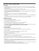
6. Neutral Latch Levers: Pivoted inside each handle there is a neutral latch lever which works with each of the
traction/steering levers. When either of the traction/steering levers is squeezed and its neutral latch lever
pushed forward and engaged in the neutral lock position, the traction/steering lever is held in a position where
its pump should not be sending any oil to the wheel drive motor. (If this is not the case, see Initial Adjustments
6 and 7.) The neutral latch levers should be engaged in the neutral lock position before starting the engine.
The hardware for the neutral lock latches should be snug to maintain the latches in the “on” or “off” positions
when set by the operator.
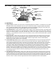
Figure 2
The left traction/steering lever shown in the neutral lock position.
7. Blade Clutch: Located on the left handle just below the control panel. This is an over-center belt clutch and
when the handle is pushed forward until it snaps to rest, it forces the idler pulley into the blade drive belt
which causes the blades to rotate. When the handle is pulled back, the pressure on the belt is relieved and
the blades will stop rotating. Figure 1 shows the electric blade clutch located on the control panel. This is an
on/off toggle switch that controls the electric blade clutch which supplies power to the cutting blades.
8. Operator Presence Levers: Located above the outer ends of the right and left handles, these levers must be
held down on the handles against spring pressure when the engine is running in order to move the ground
speed selector levers out of neutral or engage the blade clutch. Releasing the operator presence levers with
the ground speed selector levers in any position other than neutral or the blade clutch engaged will shut off
the engine.
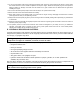
9. Freewheeling Valves: A “T” valve located on the side of each hydraulic pump when opened will permit the
mower to be pushed forward or pulled in reverse without the engine running. To override the braking force of
the hydraulic system, turn each valve counterclockwise two turns, move the mower as you wish and then turn
each valve clockwise two turns to shut the valves.
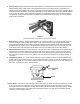
Pump
Freewheeling
Valve
Figure 3
10. Hour Meter: Located at the lower left edge of the control panel. The meter records total operating hours and
is running only when the engine is running. This hourmeter indicates hours when the engine is not running
and engine rpms when the engine is running. This unit also indicates lubrication intervals by flashing “LUBE”,
and it also indicates engine oil and filter change intervals by flashing “oil”. Both service reminders will flash
whether or not the engine is running.