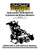
36”, 48", 52" Hydrostatic Walk-Behind Commercial Rotary Mowers Standard Professional Turf Equipment OPERATOR’S AND SERVICE MANUAL
SECTION 1: TABLE OF CONTENTS FOREWORD .................................................................................................................3 SAFETY PRECAUTIONS .............................................................................................4 SAFETY DECALS FOUND ON YOUR UNIT ................................................................6 SPECIFICATIONS.........................................................................................................8 OPERATING INSTRUCTIONS ..
SECTION 2: FOREWORD The Cub Cadet Commercial Hydro Walk-Behind Commercial Rotary Mower has been developed for use by professional landscapers, commercial lawn service companies, professional turf managers and golf course superintendents. The machine incorporates many safety features that should be studied by all operators and maintenance personnel before use. The list of safety precautions should receive particular attention.
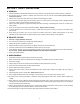
SECTION 3: SAFETY PRECAUTIONS A. GENERAL: 1. Read this Operator’s Manual before starting the mower. Study the controls and learn the proper sequence of operation. 2. Do not allow anyone to operate or maintain this machine who has not read the manual. Never permit children to operate this machine. 3. Always have your feet and hands clear of the cutter deck when starting the engine. 4. Do not remove any shields, guards, decals or safety devices.
14. If you hit a solid object while mowing, disengage the blade clutch, place the ground speed control levers in neutral, place the neutral latch levers in the neutral lock position and stop the engine. Disconnect the spark plug wire and inspect for damage. Repair any damage and make sure the blades are in good condition and the blade bolts are tight before restarting the engine. 15. Do not mow excessively steep slopes. Mow across the slope, not up and down the slope. 16.
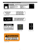
SECTION 4: SAFETY DECALS FOUND ON YOUR UNIT Keep safety decals clean. Replace any safety decal that is damaged, destroyed, missing, painted over or can no longer be read. Replacement safety decals are available through your dealer.
SAFETY DECALS FOUND ON YOUR UNIT Part Number: 01006132 Part Number: 01001038 Part Number: 01001036 Part Number: 01001035 Part Number: 02002041 Part Number: 00030635 7 Part Number: 01002171
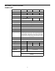
SECTION 5: SPECIFICATIONS POWER UNIT: MODEL 1536H Engine MFG 1952F --------------------- Kawasaki ---------------------- Horsepower 15HP Type 17HP 19HP ------------------- 4 Cycle Twin -------------------- Starter Air Cleaner 1748F Recoil ---------------- ----- Dual Element Dry ----- Electric ----------------- Heavy Duty Canister Lubrication --------------- Pressure with Filter --------------- Fuel Tank ---------------------- 5 gallon ----------------------- Traction Drive Two variab
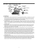
SECTION 6: OPERATING INSTRUCTIONS Choke (Some Models) Neutral Latch Lever Ground Speed Control Levers Ignition Switch Electric Blade Clutch Operator Presence Lever Engine Throttle/ Choke Left Traction Steering Lever Parking Brake Lever Standard Blade Clutch Figure 1 A. CONTROLS 1. Ignition Switch: Located in the center of the control panel between the handles. A clockwise 45° turn closes the ignition circuit.
6. Neutral Latch Levers: Pivoted inside each handle there is a neutral latch lever which works with each of the traction/steering levers. When either of the traction/steering levers is squeezed and its neutral latch lever pushed forward and engaged in the neutral lock position, the traction/steering lever is held in a position where its pump should not be sending any oil to the wheel drive motor. (If this is not the case, see Initial Adjustments 6 and 7.
B. INITIAL ADJUSTMENTS 1. Disconnect the spark plug wire. 2. Check the tire pressure. Drive Wheels should be inflated to 25 psi. Caster Wheels should be inflated to 15 psi. Note: New tires are overinflated in order to properly seat the bead to the rim. 3. Check that all nuts, bolts and screws are tight. 4. Check the tension of the deck drive belts: a. Remove the deck cover shield and engage the blade clutch. b. Make sure the belts clear the belt guides by 1/8" to 1/4". c.
C. BREAK-IN AND OPERATION 1. Make certain you thoroughly understand all of the safety precautions before you attempt to operate this machine. 2. Check the engine oil level. Fill to the proper level with straight 10W40 engine oil rated for service SE or SF. 3. Check the hydraulic oil level. Remove the fill cap and make sure the hydraulic oil level is up to the bottom of the strainer screen. Leave this air space for expansion. If the hydraulic oil level is low, fill with a good grade of SAE 20W50 engine oil.
12. To stop the mower’s forward motion, squeeze both traction/steering levers until the mower stops and place the neutral latch levers into the neutral lock position. 13. Before moving into reverse, the mower’s forward motion should be completely stopped. 14. Practice operating the mower and as you gain confidence, move the ground speed selector levers forward to two thirds full speed. Mow until comfortable and confident with the controls and then return the mower to the shop.
SECTION 8: MAINTENANCE WARNING: Disconnect the spark plug wire to prevent the engine from accidentally starting before performing any maintenance on this mower. A. GENERAL MAINTENANCE: 1. If the mower must be tipped on its side for maintenance, first drain the fuel from the fuel tank, the oil from the engine’s crankcase and the hydraulic oil from the supply tank. 2. Be careful not to spill oil on any of the belts. 3. Do not tamper with the engine’s governor settings.
D. LUBRICATION CHART: NUMBER OF GREASING POSITIONS ITEM DESCRIPTION DAILY 2 A Cutter Blade Spindle Bearings EVERY 40 HOURS 2 2 2 1 B C D Caster Wheel Bearing Caster Wheel Pivot Shafts Deck Idler Pulley Pivot Arms Blade Clutch Bellcrank Pivot Float Deck Mower Gear Deck Mower Figure 4 E. ENGINE MAINTENANCE: For detailed maintenance instructions for the engine on your mower, see the Engine Manual packed with your mower. F.
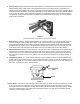
G. MOWER MAINTENANCE 1. TO CHANGE A BLADE: a. Remove the deck cover. b. Tip the mower back and block up the front of the deck. See Figure 5. c. Place one wrench on the hex head bolt under the blade. Use a second wrench to remove the nut on top of the spindle pulley. d. Remember the number of blade spacers both above and below the spindle. e. Remove the long (5/8" x 9-1/2") blade bolt for fixed decks and (3/4" x 7") blade bolt for float decks, the flat washer, the blade and the blade spacers.
d. Loosen the two belt guides under the engine deck and rotate them out of the way. Figure 7 e. Slip the long blade drive belt off of the pulleys. f. Loosen the idler pull rod which holds the idler pulley tight against the short blade drive belt. See Figure 7. g. Remove the short blade drive belt from the pulleys. h. Place a new short blade drive belt back on the pulleys and tighten the idler pull rod to hold the idler pulley tight against the belt. i.
3. INSTALLATION AND REMOVAL OF MOWER FLOAT DECK 1. 2. 3. 4. 5. Power Unit Frame Tube Stop Tabs Mower Deck Channel Retaining Pin U-Bracket PREPARATION Place the mower deck in front of the power unit on a level surface. Turn off power take-off (PTO), turn off engine and remove key from ignition switch. CAUTION: The mower deck and power unit must be placed on a hard, level surface. WARNING: Disengage the PTO, stop engine and remove key to avoid accidental starting and injury.
INSTALLING THE MOWER DECK WARNING: Disengage PTO, stop engine and remove key to avoid accidental starting and injury. WARNING: When handling the mower deck, be careful not to cut yourself on the sharp blades. 1. Lift one side of the mower deck to achieve the desired cutting height. 2. Push the button in the center of the handle of each of the retaining pins to insert the retaining pins through the appropriate front and rear height adjustment holes in the mower deck channel.
REMOVING THE MOWER DECK WARNING: Disengage PTO, stop engine and remove key to avoid accidental starting and injury. WARNING: When handling the mower deck cover, be careful not to cut yourself on the sharp blades. 1. Remove the center mower deck cover by first removing the two large wing nuts. 2. Remove the PTO belt. 3. Lift one side of the mower deck. 4. Push the button in the center of the handle of each of the two retaining pins supporting this side of the mower deck. Remove the pins. 5.
4. TO CHANGE THE PUMP DRIVE BELT: See Figure 8. a. Make sure the blade clutch is disengaged. Figure 8 b. Working under the engine deck, take the long blade drive belt off of the engine pulley. c. Loosen the locknut holding the pump drive belt idler pulley in place and slide the pulley away from the pump drive belt. d. Remove the old belt and mount a new belt on the pulleys. e. Slide the idler pulley back onto the belt and tighten the locknut holding it in place.
SECTION 9: REPLACEMENT PARTS SUGGESTED MOWER REPLACEMENT PARTS Part No. Description 00021871 Rotary Blade, 16-1/2" Fixed 00050125 Rotary Blade, 18" 01007591 Blade Bolt 5/8" 00011807 BladeNut 5/8" 01007577 Blade Spacer, .630 x 1.50 x 1.
SLOPE GAUGE DO NE , RE PRE S E NTIN G A 15 °S LOP E OR A FENCE POST A CORNER OF A BUILDING A POWER POLE SIGHT AND HOLD THIS LEVEL WITH A VERTICAL TREE USE THIS PAGE AS A GUIDE TO DETERMINE SLOPES WHERE YOU MAY NOT OPERATE SAFELY. FOL ND O T TED LI 15° WARNING Do not mow on inclines with a slope in excess of 15 degrees (a rise of approximately 2-1/2 feet every 10 feet). A riding mower could overturn and cause serious injury.
MANUFACTURER’S LIMITED WARRANTY FOR CUB CADET COMMERCIAL WIDE AREA WALK-BEHIND COMMERCIAL MOWER IMPORTANT: To obtain warranty coverage owner may be required present proof of purchase and applicable maintenance records to the servicing dealer. Please see the operator’s manual for information on required maintenance and service intervals. In addition, Cub Cadet may deny warranty coverage if the hour meter, or any part thereof, is altered, modified, disconnected or otherwise tampered with.