Safe Operation Practices • Assembly & Set-Up • Controls & Operation • Product Care Operator’s Manual Z-Force Steering Wheel Table of Contents Important Safe Operation Practices...................... 2 Product Care............................................................17 Assembly & Set-Up................................................... 7 Parts/Warranty............... See Separate Supplement Controls & Operation..............................................
Important Safe Operation Practices WARNING This symbol points out important safety instructions which, if not followed, could endanger the personal safety and/or property of yourself and others. Read and follow all instructions in this manual before attempting to operate this machine. Failure to comply with these instructions may result in personal injury. When you see this symbol.
27. 28. 29. Use only accessories and attachments approved for this machine by the machine manufacturer. Read, understand and follow all instructions provided with the approved accessory or attachment. Data indicates that operators, age 60 years and above, are involved in a large percentage of riding mower-related injuries. These operators should evaluate their ability to operate the riding mower safely enough to protect themselves and others from serious injury. 3.
b. c. When practical, remove gaspowered equipment from the truck or trailer and refuel it on the ground. If this is not possible, then refuel such equipment on a trailer with a portable container, rather than from a gasoline dispenser nozzle. Keep the nozzle in contact with the rim of the fuel tank or container opening at all times until fueling is complete. Do not use a nozzle lock-open device. 6. 7. Keep all nuts, bolts, and screws tight to be sure the equipment is in safe working condition. 8.
Safety Symbols This page depicts and describes safety symbols that may appear on this product. Read, understand, and follow all instructions on the machine before attempting to assemble and operate. Symbol Description READ THE OPERATOR’S MANUAL(S) Read, understand, and follow all instructions in the manual(s) before attempting to assemble and operate DANGER — ROTATING BLADES Never carry passengers. Never carry children, even with the blades off.
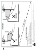
Section 2 — Important Safe Operation Practices Figure 1 line Figure 2 (TOO STEEP) 15° Slope Do not operate machine on slopes in excess of 15 degrees. All slopes require extra caution. If you cannot back up the slope or if you feel uneasy on it, do not mow it. Always mow up and down slopes, never across the face of slopes. WARNING! Slopes are a major factor related to tip-over and roll-over accidents which can result in severe injury or death. To check the slope, proceed as follows: 1.
2 Assembly & Set-Up Thank You If applicable, the power testing information used to establish the power rating of the engine equipped on this machine can be found at www.opei.org or the engine manufacturer’s web site. Thank you for purchasing this product. It was carefully engineered to provide excellent performance when properly operated and maintained. Please read this entire manual prior to operating the equipment. It instructs you how to safely and easily set up, operate and maintain your machine.
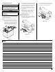
3. Rotate the seat into position and secure the seat into place with the previously removed shoulder screws and flange lock nuts. Be careful not to crimp or damage the wire harness while installing the seat. See Figure 2-4. Adjusting the Seat 1. • Operator’s forearms should be approximately horizontal. To adjust the position of the seat, push the seat adjustment lever to the left. See Figure 2-6. • Operator’s back should stay in contact with the seat back.
Connecting the Battery Cables 2. Remove the plastic cover, if present, from the negative battery terminal and attach the black cable to the negative battery terminal (–) with the bolt (a) and hex nut (b). See Figure 2-9. 3. Position the red rubber boot (c) over the positive battery terminal to help protect it from corrosion.
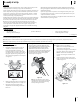
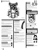
3 Controls & Operation Brake Pedal (F) The brake pedal is located on the left front side of the running board. The brake pedal can be used for sudden stops or setting the parking brake. (B) (C) (A) (F) (R) (D) Note: The brake pedal must be fully depressed to activate the safety interlock switch when starting the rider. (N) Ignition Module (G) (E) (K) (O) WARNING (Q) (H) (G) (P) † (J) (L) Never leave a running machine unattended.
When engaged, the two rods open a bypass within the hydrostatic transmissions, which allows the tractor to be pushed short distances by hand. Refer to the Assembly & Set-Up section for instructions on using the bypass feature. CAUTION Never tow your tractor. Towing the tractor with the rear wheels on the ground may cause severe damage to the transmissions. Cup Holder (J) The cup holder is located to the left of the operator’s seat on the LH console.
Operation Safety Interlock Switches c. General Safety This tractor is equipped with a safety interlock system for the protection of the operator. If the interlock system should ever malfunction, do not operate the tractor. Contact your Cub Cadet dealer. Examine the belts for cuts, fraying, and excessive wear. Replace if any of these are detected. d. Replace the deck cover. • • RECEIVE INSTRUCTION — Entirely read this operator’s manual. Learn to operate this machine SAFELY.
7. Turn the ignition key clockwise to the START position. After the engine starts, release the key. It will return to the NORMAL MOWING position. Place the PTO switch in the disengaged position. 2. Engage the parking brake. 3. Move the throttle to the SLOW position and allow the engine to idle for about one minute. 4. As the engine warms up, gradually push the choke control downward. Turn the ignition key to the STOP position and remove the key from the ignition switch.
6. The REVERSE CAUTION MODE (B) remain activated until: a. b. will Mowing To help avoid blade contact or a thrown object injury, keep bystanders, helpers, children and pets at least 75 feet from the machine while it is in operation. Stop machine if anyone enters the area. The operator leaves the seat. Driving On Slopes Refer to the slope gauge in the Safe Operation Practices section to help determine slopes where you may not operate safely.
4 Product Care Maintenance Schedule Before Each use Check Intake Screen/Clean as Needed Check & Clean Engine Cooling Fans for Debris Check Engine Oil Level Check Air Filter for Dirty, Loose or Damaged Parts Clean Transmission Cooling Slots After First 5 Hours Every 10 Hours Every 25 Hours Every 50 Hours P P P P P Prior to Storing See Engine Manual P P P P P P P P Clean Battery Terminals Grease All Lubrication Points Check Blades/Sharpen or Replace as Needed Check Tire Pressure Lube Front Wheels C
Note: This Operator’s Manual covers several models. Tractor features may vary by model. Not all features in this manual are applicable to all tractor models and the tractor depicted may differ from yours. 2. Locate the oil drain hose (a) on the right side of the engine. See Figure 4-1. Lubrication WARNING! Before lubricating, repairing, or inspecting, always disengage PTO, set parking brake, stop engine and remove key to prevent unintended starting. Troubleshooting Excessive vibration 1. • 2.
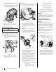
3. Pull back the lock collar (a) of the nozzle adapter (b) and push the nozzle adapter (b) onto one of the deck wash nozzles (c) at either end of the tractor deck. Release the lock collar (a) to lock the nozzle adapter (b)on the deck wash nozzle (c). See Figure 4-4. General Battery Information WARNING Should battery acid accidentally splatter into the eyes or onto the skin, rinse the affected area immediately with clean cold water. If there is any further discomfort, seek prompt medical attention.
2. If storing the tractor for 30 days or more: a. To prevent gum deposits from forming inside the engine’s carburetor and causing possible malfunction of the engine, the fuel system must be either completely emptied, or the gasoline must be treated with a stabilizer to prevent deterioration. WARNING Fuel left in the fuel tank deteriorates and will cause serious starting problems. b. • Read the product manufacturer’s instructions and recommendations.
1. 2. Visually check the distance between the front gauge wheels and the ground. If the gauge wheels are near or touching the ground, they should be raised. If more than 1⁄2” above the ground, they should be lowered. 3. Remove the lock nut (a) securing one of the front gauge wheel (b) hex screws (c) to the deck. Remove the front gauge wheel (b), hex screw (c) and spacer (d). See Figure 4-8.
Charging the Battery 4. Releasing belt tension with the idler pulley: a. Test and, if necessary, recharge the battery after the tractor has been stored for a period of time. • A voltmeter or load tester should read 12.6 volts (DC) or higher across the battery terminals. See Figure 4-10. Voltmeter Reading State of Charge Charging Time 12.7 100% Full Charge 12.4 75% 90 Min. 12.2 50% 180 Min. 12.0 25% 280 Min. c.
Deck Installation 2. Install the deck on the tractor as follows: 1. 2. 3. Remove the hex washer screws (a) securing the belt covers (b) to the deck. See Figure 4-15. Place the deck lift handle in the highest mowing position See Figure 4-11. (b) (a) Tractor Blade Care (a) WARNING (a) Before performing any maintenance, place the PTO switch in the “OFF” position, engage the parking brake lever, turn the ignition key to the “OFF” position and remove the key from the switch.
Notes 4
Medidas de seguridad • Armado e instalación • Controles y funcionamiento • Cuidado del producto Manual del Operador Modelo con volante Z-Force Índice Medidas importantes de seguridad....................... 2 Cuidado del producto............................................ 17 Armado e Instalación ............................................. 7 Piezas/Garantía..........Consulte el suplemento que Controles y Funcionamiento................................
2 Importantes medidas de seguridad ADVERTENCIA Este símbolo indica instrucciones de seguridad importantes que, de no seguirse, pueden poner en peligro su seguridad personal y/o material y la de otras personas. Lea y cumpla todas las instrucciones de este manual antes de intentar hacer funcionar esta máquina. El incumplimiento de estas instrucciones puede producir lesiones personales.
27. 28. 29. Utilice solamente accesorios e implementos aprobados para esta máquina por su fabricante. Lea, comprenda y siga todas las instrucciones incluidas con el accesorio o implemento aprobado. Los datos indican que los operadores de 60 años y más participan de un gran porcentaje de lesiones relacionadas con tractores cortacésped. Estas personas deben evaluar su capacidad para operar el tractor de manera suficientemente segura para protegerse a sí mismos y a otros de lesiones graves.
b. c. Cuando sea conveniente, retire el equipo a gasolina del camión o remolque y llénelo sobre el suelo. Si esto no es posible, llene el equipo en un remolque con un recipiente portátil, en vez de hacerlo desde un pico dispensador de gasolina. En todo momento, mantenga el pico en contacto con el borde del depósito de combustible o con la abertura del recipiente, hasta terminar la carga. No utilice un dispositivo de apertura/ cierre del pico. Servicio general 1. 2. 3. 4. 5. 4 6. 7.
Símbolos de seguridad En esta página se presentan y describen los símbolos de seguridad que pueden aparecer en este producto. Lea, comprenda y siga todas las instrucciones incluidas en la máquina antes de intentar armarla y hacerla funcionar. Símbolo Descripción LEA LOS MANUALES DEL OPERADOR Lea, entienda y siga todas las instrucciones incluidas en los manuales antes de intentar armar la unidad y hacerla funcionar. PELIGRO — CUCHILLAS GIRATORIAS Nunca lleve pasajeros.
6 Sección 2 — Importantes medidas de seguridad Figura 1 Línea ntos de pu a 15° Pendiente de 15 ¡ADVERTENCIA! Las pendientes son uno de los principales factores asociados a los accidentes por tumbos y vuelcos que pueden producir lesiones graves o la muerte. No utilice la máquina en pendientes de más de 15°. Todas las pendientes exigen precaución adicional. Si no puede retroceder por la pendiente o si no se siente seguro, no realice ningún corte.
2 Armado e Instalación Muchas gracias Si corresponde, la información sobre las prueba de potencia utilizada para determinar la potencia nominal del motor equipado en esta máquina se puede consultar en www.opei.org o en el sitio web del fabricante del motor. Gracias por comprar este producto. Ha sido cuidadosamente diseñado para brindar excelente rendimiento si se lo hace funcionar y se lo mantiene correctamente. Por favor lea todo este manual antes de hacer funcionar el equipo.
3. Gire el asiento hasta la posición deseada y asegúrelo en su lugar con los tornillos de reborde y las tuercas de seguridad con brida que extrajo antes. Tenga cuidado de no doblar o dañar el cableado mientras instala el asiento. Vea la Figura 2-4. Ajuste del asiento 1. Para ajustar la posición del asiento, empuje la palanca de ajuste del asiento hacia la izquierda. Vea la Figura 2-6. 6. 2 • Los antebrazos del operador deben estar en posición aproximadamente horizontal.
Conexión de los cables de la batería 2. Retire la cubierta plástica, si está presente, del borne negativo de la batería y una el cable negro al borne negativo de la batería (–) utilizando el perno (a) y la tuerca hexagonal (b). Vea la Figura 2-9. 3. Coloque el capuchón de goma rojo (c) sobre el borne positivo de la batería para protegerlo contra la corrosión.
3 Controles y funcionamiento Pedal de freno (F) El pedal del freno está ubicado del lado delantero izquierdo del estribo. El pedal del freno se puede usar para detenciones repentinas o para accionar el freno de estacionamiento. (B) (C) (A) (F) (R) Nota: El pedal del freno se debe presionar completamente para accionar el interruptor de interbloqueo de seguridad cuando se inicia la marcha.
Cuando están engranadas, las dos varillas abren una derivación dentro de las transmisiones hidrostáticas, lo cual permite empujar el tractor a mano a lo largo de distancias cortas. Consulte la sección Armado e Instalación para obtener instrucciones sobre el uso de la función de derivación. PRECAUCIÓN Nunca remolque su tractor. Si se remolca el tractor con las ruedas traseras apoyadas en el suelo se pueden causar daños graves a las transmisiones.
Funcionamiento Seguridad general • • RECIBA LAS INSTRUCCIONES - Lea este manual del operador en su totalidad. Aprenda a usar esta máquina DE MANERA SEGURA. No se arriesgue a quedar expuesto a LESIONES o a la MUERTE. Solamente se debe permitir operar este tractor a quienes se hayan familiarizado a fondo con el uso del mismo. Antes de arrancar el motor o de empezar a operar, familiarícese con los controles. El operador debe estar en el asiento del operador.
7. Gire la llave de encendido en el sentido de las agujas del reloj hasta la posición START (encendido). Una vez que arranque el motor, suelte la llave. Volverá a la posición NORMAL MOWING (corte normal). PRECAUCIÓN NO mantenga la llave en la posición START (arranque) durante más de diez segundos por vez. Si lo hace, puede ocasionar daños al arrancador eléctrico del motor. 8. Para parar el motor Coloque el interruptor de la toma de fuerza (PTO) en la posición desactivada. 2. Aplique el freno de mano.
6. El MODO DE PRECAUCIÓN EN MARCHA ATRÁS permanece activado hasta que (B) a. b. : Corte de césped Para tratar de evitar el contacto con las cuchillas o una lesión por un objeto que sea arrojado, mantenga a los observadores, ayudantes, niños y mascotas alejados al menos 75 pies de la máquina mientras está funcionando. Pare la máquina si alguien ingresa a la zona. El operador deja el asiento.
4 Cuidado del producto Programa de Mantenimiento Antes de cada uso Después de las primeras 5 horas Cada 10 Horas Cada 25 Horas Cada 50 Horas Cada 100 Horas Antes de almacenar Revise el filtro de admisión/limpie si corresponde P P Revise y limpie de residuos los ventiladores de refrigeración del motor P P P P P Controle el nivel de aceite del motor Revise si el filtro de aire está sucio, flojo o tiene piezas dañadas Limpie las ranuras de enfriamiento de la transmisión P P P P P P Limpie los b
Nota: Este manual del operador abarca numerosos modelos. Las características del tractor pueden variar según los modelos. No todas las características que se incluyen en este manual se aplican a todos los modelos de tractor y la máquina que se ilustra aquí puede diferir de la suya. 2. Ubique la manguera de drenaje de aceite (a) del lado derecho del motor. Vea la Figura 4-1. Solución de Problemas (b) Excesiva vibración 1. Cuchilla de corte floja o descentrada. • Apriete la cuchilla y el husillo. 2.
3. Tire hacia atrás el collarín de ajuste (a) del adaptador del pico (b) y empuje el adaptador del pico (b) hacia uno de los picos de lavado de la plataforma (c) de cualquiera de los dos extremos de la plataforma de corte. Suelte el collarín de ajuste (a) para trabar el adaptador en el pico (b) en el pico de lavado de la plataforma (c). Vea la Figura 4-4.
2. Si guarda el tractor por 30 días o más: a. Para evitar que se formen depósitos de goma dentro del carburador del motor y posibles desperfectos en el motor, el sistema de combustible debe ser vaciado completamente, o se debe tratar la gasolina con un estabilizador para evitar el deterioro. Retiro del tractor del lugar de guarda 1. Controle el nivel de aceite de motor. 2. Cargue totalmente la batería e infle los neumáticos a la presión recomendada. 3.
1. 2. Controle visualmente la distancia entre las ruedas de calibración delanteras y el suelo. Si las ruedas de calibración están cerca del suelo o lo tocan, es necesario levantarlas. Si las ruedas de calibración se encuentran a más de 1⁄2” del suelo, es necesario bajarlas. 3. Retire la tuerca de seguridad (a) que fija uno de los tornillos hexagonales (c) de las ruedas de calibración delanteras (b) a la plataforma. Retire la rueda de calibración (b), el tornillo hexagonal (c) y el espaciador (d).
Carga de la batería 4. • a. Un voltímetro o medidor de carga debería dar una lectura de 12.6 voltios (CC) o más en todos los bornes de la batería. Vea la Figura 4-10. Lectura del voltímetro Estado de la carga Tiempo de carga 12,7 100 % Carga completa 12,4 75 % 90 minutos 12,2 50 % 180 minutos 12,0 25 % 280 minutos c. Para aflojar la tensión de la correa con la polea loca: Si el tractor ha estado guardado durante un tiempo, pruebe la batería y, si es necesario, recárguela.
Instalación de la plataforma 2. Instale la plataforma sobre el tractor de la siguiente forma: 1. Coloque la manija de elevación de la plataforma en la posición de corte más elevada. Vea la Figura 4-11. 2. Deslice la plataforma debajo del tractor del lado derecho del mismo, alineando las ménsulas de suspensión de la plataforma y los brazos de elevación de la plataforma. 3. Retire los tornillos de cabeza hexagonal con arandela (a) que sujetan las cubiertas de las correas (b) a la plataforma.
Notas 20