® OPERATOR'S MANUAL IES TRACTOR Model Number RZT 42 w/42" Mower Deck IMPORTANT: READ SAFETY RULES AND INSTRUCTIONS CAREFULLY Warning: This unit is equipped with an internal combustion engine and should not be used on or near any unimproved forestcovered, brush-covered or grass-covered land unless the engine's exhaust system is equipped with a spark arrester meeting applicable local or state laws (if any), If a spark arrester is used, it should be maintained in effective working order by the operator
TABLE OF CONTENTS TRACTOR PREPARATION .................................................................................................... IMPORTANT SAFE OPERATION PRACTICES .................................................................... SAFETY DECALS AND LABELS ........................................................................................... SLOPE GAUGE ...................................................................................................................... TO THE OWNER ........
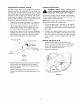
POSITION DRIVE CONTROL LEVERS CONNECT THE BATTERY The drive control levers of the tractor are lowered for shipping purposes. To accomplish this, the flange lock nut, hex screw, and flat washer normally used to secure each control lever to its pivot bracket are removed. The hardware is then installed in the slotted hole of each control lever for shipment. The control levers must be moved to their operating position.
WARNING • The engine exhaust, some of its constituents, and certain vehicle components contain or emit chemicals known to the State of California to cause cancer, birth defects or other reproductive harm. • This unit is equipped with an internal combustion engine and should not be used on or near any unimproved forest-covered, brush-covered, or grass-covered land unless the engine's exhaust system is equipped with a spark arrester meeting applicable local or state laws (if any).
13.Mowonlyin daylightor goodartificiallight. 14.Do not operatethe machinewhile under the influenceofalcoholor drugs. 15.Watchfortrafficwhenoperatingnearor crossing roadways. 16.Use extra carewhen loadingor unloadingthe machineintoa trailerortruck.Thisunitshouldnot bedrivenupor downa rampontoa trailerortruck under power,becausethe unit could tip over causingseriouspersonalinjury.Theunitmustbe pushedmanuallyon a rampto load or unload properly. 17.
5. Never allow children under 14 years old to operatethe machine.Children14yearsandover shouldonly operatethe machineunderclose parentalsupervision andproperinstruction. 6. Useextracarewhenapproaching blindcorners, shrubs,treesor otherobjectsthatmayobscure yourvisionof a childor otherhazard. 7. Removethe key when the machineis left unattended to preventunauthorized operation. ,_ IV. SERVICE , Use extreme care in handling gasoline and other fuels. They are extremely flammable and the vapors are explosive.
SAFETY DECALS AND LABELS Keep product safety graphics (decals) clean• Replace any safety graphic that is damaged, destroyed, missing, painted over or can no longer be read.
USE THIS PAGE AS A GUIDE TO DETERMINE SLOPES WHERE YOU MAY NOT OPERATE SAFELY. SIGHT AND HOLD THIS LEVEL WITH A VERTICAL TREE I_ I .... mR " " " " .. A POWER POLE i .91 I I " ".. , "9 A CORNER OF A BUILDING OR A FENCE POST OLD ON ,....,,..uOT_,_ I , . ,._,v.IlAir, == " v L_ .. A s co !t 15° ,_ WARNING Do not mow on inclines with a slope in excess of 15 degrees (a rise of approximately 2-1/2 feet every 10 feet). A riding mower could overturn and cause serious injury.
TO THE OWNER This Operator's Manual is an important part of your new tractor. The information contained in this manual has been prepared in detail to help you better understand the features, correct operation, adjustments, and maintenance of your tractor. The performance and dependability of this tractor rely greatly on the manner in which it is operated and maintained. Therefore, it is recommended that all operators of the tractor carefully read this manual and fully understand its operation.
SECTION 1" CONTROLS AND FEATURES / K Figure 6 A. Deck Height Index B. Deck Lift Handle C. RH and LH Drive Control Levers D. Ignition Switch E. PTO Switch F. Transmission G. Cup Holder Bypass Rod (Not Shown) H. Storage Tray J. Seat Adjustment Lever (Not Seen) K. Fuel Tank Cap L. Hour Meter/Indicator M. Throttle Control Panel N.
NOTE: References to LEFT, RIGHT, FRONT, and REAR indicate that position on the tractor when facing forward while seated in the operator's seat. A. E. Power Take-Off (PTO) Switch The PTO switch is located on the RH console to the right of the operator's seat. Deck Height Index The deck height index consists of six index notches located on the front/right of the seat box frame.
WARNING: Never fill the fuel tank when the engine is running. If the engine is hot from recently running, allow to cool for several minutes before refueling. Highly flammable gasoline could splash onto the engine and cause a fire. L. Hour Meter/Indicator check the battery and charging system for possible causes and/or contact your Cub Cadet dealer. Oil Pressure Indicator • Panel The hour meter/indicator panel is located on the LH console to the left of the operator's seat.
Pull the throttle control handle rearwardto decrease theenginespeed. When starting the engine, push the control handlefully forwardintothe "CHOKE"position. Referto Figure10.Afterstartingandwarmingthe engine,movethe controlhandlerearwarduntil youfeelit movepastthechokedetent. N. Parking Brake Engagement Lever • • RECEIVE INSTRUCTION - Read the operator's manual. Learn to operate this machine SAFELY. Don't risk INJURY or DEATH.
• • • • • • Gasohol(upto 10%ethylalcohol,90%unleaded gasolineby volume)is an approvedfuel. Other gasoline/alcohol blendsarenotapproved. MethylTertiaryButylEther(MTBE)andunleaded gasolineblends(upto a maximumof 15%MTBE by volume)are approvedfuels. Othergasoline/ etherblendsarenotapproved. Checkthe engineoil level. Cleantheaircleanerelementif necessary. Checkthetire inflationpressures. Adjustthe seatfor operator'smaximumcomfort, visibilityandfor maintaining completecontrolof thetractor.
COLDWEATHER STARTING • Whenstartingtheengineattemperatures nearor belowfreezing,ensurethecorrectviscositymotor oil is usedin the engineandthe batteryis fully charged.Starttheengineasfollows: • Be surethe batteryis in goodcondition.A warm batteryhasmuchmorestartingcapacitythana coldbattery. • Use fresh winter grade fuel. Winter grade gasolinehashighervolatilityto improvestarting. Donotusegasolineleftoverfromsummer. • Followthe previousinstructionfor STARTING THEENGINE.
• Movethe RHandLHdrivecontrolleversinward intheneutralposition.SeeFigure12. DRIVING FORWARD Faster Control Lever Moved Inward and in Neutral Slower Neutral Position 0 Figure 13 Figure 12 • NOTE: If the control levers are not even in the neutral position, refer to Section 3 and adjust the levers so that they are even. • move the _k of travel, we recommend performing WARNING: When reversing the direction gradual 'U' turns where possible.
Toturntothe right,movetherightdrivecontrol leverrearward ofthe leftlever.SeeFigure15. IMPORTANT: Always maintain your grasp on the drive control levers. Do not release the levers to slow the tractor or to return to neutral. FORWARD RIGHT TURN Turning While Driving Rearward • To turn the tractor while driving rearward, move the control levers as necessary so that one lever is forward of the other. The tractor will turn in the direction of the forward control lever.
STOPPING THE TRACTOR Executing a Zero Turn _ the tractor MUST BE STOPPED. WARNING: When executing a zero turn, Executing a zero turn while the tractor is moving can significantly reduce your control of the tractor and will cause severe turf defacement to occur. • Stop the forward or reverse motion of the tractor by moving the two drive control levers to neutral. • To turn clockwise, move the left control lever forward while simultaneously moving the right control lever rearward. See Figure 19.
USING THE MOWER DECK IMPORTANT: When stopping the tractor reason while on a grass surface, always: WARNING: Make certain the area to be mowed is free of debris, sticks, stones, wire or other objects that can be thrown by the rotating blades. • • • Mow across slopes, not up and down. If mowing a slope, start at bottom and work upward to ensure turns are made uphill. • On the first pass pick a point on the opposite side of the area to be mowed.
SECTION 3: ADJUSTMENTS ADJUSTING THE OPERATORS SEAT To adjust the position of the seat, move and hold the seat adjustment lever toward the left. Slide the seat forward or rearward to the desired position; then release the adjustment lever. Make sure seat is locked into position before operating the tractor. See Figure 21. • Reposition the control lever to align with the other set of holes in the pivot bracket and insert the shoulder screw removed earlier.
SECTION 4: MAINTENANCE Perform all maintenance given in the instructions. procedures at the intervals RECOMMENDED SAEVISCOSITY GRADES -30°C ENGINE MAINTENANCE Engine maintenance procedures must be performed at the intervals given in the following instructions. Checking -20°C -10°C 0°C 10°C 30°C 40°C 0 _k I Engine Oil Level 20°C Check engine oil level before each use as follows: • Place the tractor on a flat surface and stop the engine.
• • • • Applya thincoator newoil onthe rubbergasket ofthenewoilfilter. Installthe newoilfilteronthefilteradapter.Hand tightenuntilthefiltergasketcontactsthe adapter, thentightenthefilteranadditional3/4-1turn. Refillthe enginewith the propertype oil. The engineoil capacityis approximately (1.6qts.;1.5 liters). Reinstallthe dipstick/oilfill cap and pushfirmly intoplace. Remove the air cleaner element with the integral rubber seal. See Figure 25. Air Cleaner Element Foam Precleaner Air Cleaner Cover \ En
CleanEngineCoolingAreas To ensure proper cooling,make sure the grass screen,coolingfins,and otherexternalsurfacesof theenginearekeptcleanatalltimes. Annuallyor every100hoursof operation(moreoften underextremelydusty,dirtyconditions),removethe blowerhousingandcoolingshrouds.Cleanthecooling fins and externalsurfacesas necessary.Make surethe coolingshroudsare reinstalled. Torquethe blowerhousingscrewsto 65in. Ib.(7.5N.m).
BATTERY REMOVAL BATTERY MAINTENANCE The battery is filled with battery acid and then sealed at the factory. However, even a "maintenance free" battery requires some maintenance to ensure its proper life cycle. related accessories contain lead and lead WARNING: Battery posts, terminals and compounds. Wash hands after handling. The battery is located on the right/rear of the tractor beneath the seat box frame.
LUBRICATION Afterevery10hoursof operation,usea pressurelubricatinggun to applyCub Cadet251H EP grease throughthe lubefittingsfor the frontcastorshafts, frontpivotaxle,andfrontcastorwheels. Periodicallylubricateall other pivot pointswith a qualitylubricating oil. Referto the "MOWERDECK"sectionlater in this manualfordecklubrication procedures. • TIREMAINTENANCE Checkthe tire air pressureafterevery50 hoursof operationor weekly.Keepthe tires inflatedto the recommendedpressures.
• • • If the rotationstops,adjusttheferruleupor down thecontrolrodas necessary to alignwiththe hole in the transmissioncontrolarm. Re-insertthe ferruleintothe holeinthecontrolarmandsecure withtheinternalcotterpin. If necessary,repeatthe previoustwo stepsto adjusttheothertransmission controlrod. Lowerthetractorandremovethejack. • Tighten the jam nut against the console and reposition the control lever if necessary.
TRACTORSTORAGE If your tractoris not goingto be operatedfor an extendedperiodof time(thirtydaysto approximately six months),the tractorshouldbe preparedfor storage.Storethe tractorin a dryandprotectedlocation. If storedoutside,coverthetractor(including thetires) to protectit fromthe elements.The procedures outlinedbelowshouldbeperformed whenever thetractor is placedin storage. 1. Changethe engineoil and filter followingthe instructions providedin the engineinformation at thebackofthismanual.
SECTION 5: MOWER DECK This section contains removal, installation, adjustment, and maintenance information for the 42-inch mower deck. Rolling the belt off the PTO pulley. • Using the deck lift handle, raise the deck to the upper position that allows for the most horizontal run of the belt between the deck idler pulleys and the PTO pulley on the bottom of the engine. DECK REMOVAL Remove the mower deck from the tractor as follows: 1.
7. Slide the deck forwardso that the deck front hangerrodcanbe liftedoutofthetwoslotsofthe frontdeckbracket.After liftingthe front hanger rod out of the slots,slidethe deckrearwardso thattherodcannolongerengagetheslots. 8. Usingcareto preventthe fronthangerrodfrom fallingbackintothe deckslots,gentlyslidethe cutting deck (from the right side) out from underneath thetractor. Route the backside of the belt around the fixed idler pulley of the deck. Refer to Figure 34.
LEVELINGTHEMOWERDECK Whenleveledcorrectlythe mowerdeckshouldbe levelsideto side,andshouldbe approximately a 1/8 to 1/4inchlowerinthefrontofthedeck. Sideto SideLeveling If the cuttingdeckappearsto bemowingunevenly,a sideto sideadjustmentcan be performed.Adjustif necessary asfollows: • Withthe tractorparkedon a firm,levelsurface, placethedecklifthandleinthetop notch(highest position)androtatebothbladesso thattheyare perpendicular tothetractorframe.
ADJUSTING THE GAUGE WHEELS The cutting height of the mower deck can be set in any of six height settings using the deck lift handle of the tractor. The deck heights range from 1-1/2 inches to 4 inches. The deck gauge wheel position should be approximately 1/4 to 1/2 inch above the ground when the deck is set in the desired height setting. • Attach the nozzle adapter to a standard garden hose connected to a water supply.
Thebladesmayberemovedasfollows. • Removethe deckfrombeneaththe tractor,(refer to DeckRemovalonpage28)thengentlyflipthe deckovertoexposeitsunderside. • Usea 15/16inchwrenchto holdthe hexnuton top of the spindleassemblywhenlooseningthe hexnutsecuringtheblade.A blockof woodmay beplacedbetweenthedeckhousingandthe cuttingedgeof the bladeto helpin breakingloose thehexnutsecuringtheblade.SeeFigure41. upward toward the top of the deck. Tighten the blade nuts to 70-90 ft. Ibs.
FEDERAL KOHLER CO. AND CALIFORNIA EMISSION CONTROL SYSTEMS LIMITED WARRANTY SMALL OFF-ROAD EQUIPMENT ENGINES The U.S. Environmental Protection Agency (EPA), the California Air Resources Board (CARB), and Kohler Co. are pleased to explain the Federal and California Emission Control Systems Warranty on your small off-road equipment engine. For California, engines produced in 1995 and later must be designed, built and equipped to meet the state's stringent anti-smog standards.
CALIFORNIA YOUR EMISSION CONTROL W ARRANTY RIGHTS WARRANTY AND STAT EMENT OBLIGATIONS The California Air ResourcesBoard and MTD Consumer Group Inc. are pleasedto explain the evaporative emission control system warranty on your 2007 lawn mower. In California, new lawn mower must be designed, built and equipped to meet the State's stringent anti-smog standards. MTD Consumer Group Inc.
CUB CADET LLC MANUFACTURER'S LIMITED WARRANTY RESIDENTIAL ZERO-TURN IMPORTANT: To obtain warranty coverage owner must present an original proof of purchase and applicable maintenance records to the servicing dealer. Please see the operator's manual for information on required maintenance and service intervals.