® OPERATOR'S MANUAL ,\ \\\ TRACTOR Model Number RZT 50 w/50" Mower Deck IMPORTANT: READ SAFETY RULES AND INSTRUCTIONS CAREFULLY Warning: This unit is equipped with an internal combustion engine and should not be used on or near any unimproved forestcovered, brush-covered or grass-covered land unless the engine's exhaust system is equipped with a spark arrester meeting applicable local or state laws (if any), If a spark arrester is used, it should be maintained in effective working order by the oper
TABLE OF CONTENTS TRACTOR PREPARATION .................................................................................................... IMPORTANT SAFE OPERATION PRACTICES .................................................................... SAFETY DECALS AND LABELS ........................................................................................... SLOPE GAUGE ...................................................................................................................... TO THE OWNER ........
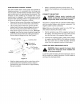
POSITION DRIVE CONTROL LEVERS • The drive control levers of the tractor are lowered for shipping purposes. To accomplish this, the flange lock nut, hex screw, and flat washer normally used to secure each control lever to its pivot bracket are removed. The hardware is then installed in the slotted hole of each control lever for shipment. The control levers must be moved to their operating position.
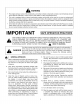
WARNING • The engine exhaust, some of its constituents, and certain vehicle components contain or emit chemicals known to the State of California to cause cancer, birth defects or other reproductive harm. • This unit is equipped with an internal combustion engine and should not be used on or near any unimproved forest-covered, brush-covered, or grass-covered land unless the engine's exhaust system is equipped with a spark arrester meeting applicable local or state laws (if any).
13. Mowonlyin daylightor goodartificiallight. 14. Do not operatethe machinewhile under the influenceofalcoholor drugs. 15. Watchfortrafficwhenoperatingnearor crossing roadways. 16. Use extra carewhen loadingor unloadingthe machineintoa trailerortruck.Thisunitshouldnot bedrivenupor downa rampontoa trailerortruck under power,becausethe unit could tip over causingseriouspersonalinjury.Theunitmustbe pushedmanuallyon a rampto load or unload properly. 17.
5. Never allow children under 14 years old to operatethe machine.Children14yearsandover shouldonly operatethe machineunderclose parentalsupervision andproperinstruction. 6. Useextracarewhenapproaching blindcorners, shrubs,treesor otherobjectsthatmayobscure yourvisionof a childor otherhazard. 7. Removethe key when the machineis left unattended to preventunauthorized operation. ,_ IV. SERVICE , Use extreme care in handling gasoline and other fuels. They are extremely flammable and the vapors are explosive.
SAFETY DECALS AND LABELS Keep product safety graphics (decals) clean. Replace any safety graphic that is damaged, destroyed, missing, painted over or can no longer be read. Replacement safety graphics are available through your dealer.
USE THIS PAGE AS A GUIDE TO DETERMINE SLOPES WHERE YOU MAY NOT OPERATE SAFELY. SIGHT AND HOLD THIS LEVEL WITH A VERTICAL TREE co 15 ° WARNING Do not mow on inclines with a slope ,n excess of 15 degrees (a rise of approximately 2-1/2 feet every 10 feet). A riding mower could overturn and cause serious injury. If operating a walk-behind mower on such a slope, it is extremely difficult to maintain your footing and you could slip, resulting in serious injury.
TO THE OWNER This Operator's Manual is an important part of your new tractor. The information contained in this manual has been prepared in detail to help you better understand the features, correct operation, adjustments, and maintenance of your tractor. The performance and dependability of this tractor rely greatly on the manner in which it is operated and maintained. Therefore, it is recommended that all operators of the tractor carefully read this manual and fully understand its operation.
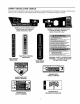
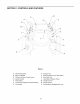
SECTION 1" CONTROLS AND FEATURES K Figure 4 A. Deck Height Index B. Deck Lift Handle C. RH and LH Drive Control Levers D. Ignition Switch E. PTO Switch F. Transmission G. Cup Holder Bypass Rod (Not Shown) H. Storage Tray J. Seat Adjustment Lever (Not Seen) K. Fuel Tank Cap L. Hour Meter/Indicator M. Throttle Control Panel N. Choke Control O.
NOTE: References to LEFT, RIGHT, FRONT, and REAR indicate that position on the tractor when facing forward while seated in the operator's seat. A. E. Power Take-Off (PTO) Switch The PTO switch is located on the RH console to the right of the operator's seat. Deck Height Index The deck height index consists of six index notches located on the front/right of the seat box frame.
WARNING: Never fill the fuel tank when the engine is running. If the engine is hot from recently running, allow to cool for several minutes before refueling. Highly flammable gasoline could splash onto the engine and cause a fire. L. Hour Meter/Indicator Oil Pressure Indicator This warning lamp indicates low engine oil pressure. If the indicator comes on while the engine is running, stop the engine immediately and check for possible causes. Do not run the engine while this indicator is illuminated.
N. ChokeControl Thechokeknobcontrolsthepositionoftheengine choke.Pulltheknobouttochoketheengine;pushthe knobintoopenthechoke. • Pull the lever fully upward and to the left; then lower into the "J" slot to engage the parking brake. • Pull the lever up out of the "J" slot and to the right; then lower completely to disengage the parking brake. O. Parking Brake Engagement Lever The parking brake engagement lever is located on the front/left of the seat box frame, and is used to engage the parking brake.
• • • • • • Gasohol(upto 10%ethylalcohol,90%unleaded gasolineby volume)is an approvedfuel. Other gasoline/alcohol blendsarenotapproved. MethylTertiaryButylEther(MTBE)andunleaded gasolineblends(upto a maximumof 15%MTBE by volume)are approvedfuels. Othergasoline/ etherblendsarenotapproved. Checkthe engineoil level. Cleantheaircleanerelementif necessary. Checkthetire inflationpressures. Adjustthe seatfor operator'smaximumcomfort, visibilityandfor maintaining completecontrolof thetractor.
Observethe hour meter/indicator panel. If the batteryindicatorlightor oil pressurelightcome on,immediately stopthe engine.Havethetractor inspectedbyyourCub Cadet dealer. • Engage the parking brake. • Move the throttle control to the SLOW position and allow the engine to idle for about one minute. • Turn the ignition key to the "OFF" position and remove the key from the ignition switch.
• Movethe RHandLHdrivecontrolleversinward inthe neutralposition.Referto Figure10. DRIVING FORWARD Faster Control Lever Moved Inward and in Neutral Slower Neutral Position 0 Figure 11 Figure 10 • NOTE: If the control levers are not even in the neutral position, refer to Section 3 and adjust the levers so that they are even.
Toturntothe right,movetherightdrivecontrol leverrearward ofthe leftlever.SeeFigure13. IMPORTANT: Always maintain your grasp on the drive control levers. Do not release the levers to slow the tractor or to return to neutral. FORWARD RIGHT TURN Turning While Driving Rearward • To turn the tractor while driving rearward, move the control levers as necessary so that one lever is forward of the other. The tractor will turn in the direction of the forward control lever.
STOPPING THE TRACTOR Executing a Zero Turn _ the tractor MUST BE STOPPED. WARNING: When executing a zero turn, Executing a zero turn while the tractor is moving can significantly reduce your control of the tractor and will cause severe turf defacement to occur. • Stop the forward or reverse motion of the tractor by moving the two drive control levers to neutral. • To turn clockwise, slowly move the left control lever forward while simultaneously moving the right control lever rearward. See Figure 17.
USING THE MOWER DECK IMPORTANT: When stopping the tractor reason while on a grass surface, always: WARNING: Make certain the area to be mowed is free of debris, sticks, stones, wire or other objects that can be thrown by the rotating blades. • • • Mow across slopes, not up and down. If mowing a slope, start at bottom and work upward to ensure turns are made uphill. • On the first pass pick a point on the opposite side of the area to be mowed.
SECTION 3: ADJUSTMENTS ADJUSTING THE OPERATORS SEAT • Reposition the control lever to align with the other set of holes in the pivot bracket and insert the shoulder screw removed earlier. Fasten with the hex insert flange lock nut and tighten until snug. • Insert the hex screw w/washer through the control lever slot and the pivot bracket.Thread the flange lock nut onto the screw, but do not tighten To adjust the position of the seat, move and hold the seat adjustment lever toward the left.
SECTION 4: MAINTENANCE ENGINE MAINTENANCE GENERAL BATTERY INFORMATION Engine maintenance procedures and schedules can be found in the engine manual that was packed with this manual. Follow those schedules for performing engine maintenance. _' Using the Engine Oil Drain Valve • Locate the oil drain valve on the left side of the • Should battery acid accidentally splatter into the eyes or onto the skin, rinse the affected area immediately with clean cold water.
• Removethe hexcapscrewandsemsnut securingtheblacknegativebatteryleadto thenegative batterypost(markedNEG).Movethecableaway fromthe negativebatterypost. • Removethe hexcapscrewandsemsnut securing the red positivebatteryleadto the positive batterypost(markedPOS). • Carefullyliftthe batteryoutofthetractor. Installthe batteryby repeating the abovestepsinthe reverseorder. WARNING:Always connect the positive BATTERY STORAGE When storing the tractor for extended periods, disconnect the negative battery cable.
TIRE MAINTENANCE IMPORTANT: The tractor will not drive with the bypass rods in the engage position. Check the tire air pressure after every 50 hours of operation or weekly. Keep the tires inflated to the recommended pressures. Improper inflation will shorten the service life of a tire. See the tire side wall for proper inflation pressures. Observe the following guidelines: • Do not inflate a tire above the maximum pressure shown on the sidewall of the tire.
TRACTOR HIGH SPEED TRACKING TRANSMISSION If the tractor tracks to one side with both drive control If the transmission drive belt becomes worn and causes the drive transmissions to slip, the drive belt must be replaced. To replace the drive belt, proceed as follows: levers fully forward, follows: adjust the control levers as Check for proper and balanced air pressure in both front and rear tires. Refill tires if necessary.
TRACTORSTORAGE If your tractoris not goingto be operatedfor an extendedperiodof time(thirtydaysto approximately six months),the tractorshouldbe preparedfor storage.Storethe tractorin a dryandprotectedlocation. If storedoutside,coverthetractor(including thetires) to protectit fromthe elements.Theprocedures outlinedbelowshouldbeperformed whenever thetractor is placedin storage. 1. Changethe engineoil and filter followingthe instructionsprovided in the engine manual packedwiththismanual.
SECTION 5: MOWER DECK This section contains removal, installation, adjustment, and maintenance information for the 50-inch mower deck. Instructions for installation and removal of the optional mulching plug are located at the end of this section. Rolling the belt off the PTO pulley. • Using the deck lift handle, raise the deck to the upper position that allows for the most horizontal run of the belt between the deck idler pulleys and the PTO pulley on the bottom of the engine.
7. Slide the deck forwardso that the deck front hangerrodcanbe liftedoutofthetwoslotsofthe frontdeckbracket.After liftingthe front hanger rod out of the slots,slidethe deckrearwardso thattherodcannolongerengagetheslots. 8. Usingcareto preventthe front hangerrodfrom fallingbackintothe deckbracketslots,carefully slide the cuttingdeck (fromthe right side)out fromunderneath thetractor. Route the backside of the belt around the fixed idler pulley of the deck. Refer to Figure 28.
LEVELINGTHEMOWERDECK Whenleveledcorrectlythe mowerdeckshouldbe levelsideto side,andshouldbe approximately a 1/8 to 1/4inchlowerinthefrontofthedeck. Sideto SideLeveling If the cuttingdeckappearsto bemowingunevenly,a sideto sideadjustmentcan be performed.Adjustif necessary asfollows: • Withthe tractorparkedon a firm,levelsurface, placethedecklifthandleinthetop notch(highest position)androtatebothouterbladessothatthey areperpendicular tothetractorframe.
ADJUSTING THE GAUGE WHEELS DECK MAINTENANCE The cutting height of the mower deck can be set in any of six height settings using the deck lift handle of the tractor. The deck heights range from 1-1/2 inches to 4 inches. The deck gauge wheel position should be approximately 1/4 to 1/2 inch above the ground when the deck is set in the desired height setting.
Mower Blade Care WARNING: Before performing any maintenance, place the PTO switch in the "OFF" position, engage the parking brake lever, turn the ignition key to the "OFF" position and remove the key from the switch. When servicing the mower deck, be careful not to cut yourself on the sharpened blades. Hex Nut 5/16" Wrench The cutting blades must be kept sharp at all times. Sharpen the cutting edges of the blades evenly so that the blades remain balanced and the same angle of sharpness is maintained.
ENGINE MANUAL A Kawasaki engine is used on this RZT tractor model. The following section is a reproduction of the Kawasaki engine manual that applies to the engine. Read this manual in its entirety. Observe all warnings and follow all operation and maintenance instructions provided in the manual. NOTE: Although the engine manual provides Kawasaki service contact information, always first contact Cub Cadet dealer if you experience engine problems or have questions regarding the engine.
READ THIS FIRST For your safety, read this Owner's Manual and understand it thoroughly before operating this ENGINE. DO NOT run the engine in a closed area. Exhaust gas contains carbon monoxide, an odorless and deadly poison. Gasollne is extremely flammable and can be explosive under certain condition. Stop engine and allow the engine to cool before refueling. DO NOT smoke.
Cali_nia All Other States Model Year - 2002 and _ater Model Year - 2001 and later Durabil_ Per=_ - 500 hours Durab,ity Period - 1 000 houm(Category A) * ffyour engine has an assigned emissions durability period it will be located on the certification ta_l attached _ the engine (IMPORTANT ENGINE INFORMATION), High Altitude Pertinence Adjustment Information To improvethe EMISSIONS CONTROL PERFORMANCE of e_ines operated above 1,000 met_ (3 300 feet), K_asa_ recornmendsthe followi_ EnvironmentalProtection
FOREWORD We wish to thank you for piJrCh_singthis IKJ_esakiengine. Please read this Owner's Manual carefully before starting your new engine so Ihat you will be thoroughly familiarwith the properoperationof your engine'scontrol its features, capabilitiesand limitations. Also read the manual of the equipmentto whichthis engine is attached. To ensure a long,trouble-freelife for yourengine, give it the proper care and maintenancedescribedin this manual.
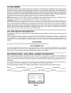
8 GENERAL INFORMATION GENE L INFORMATION Location of Safety Related Labels MAINTENANC ENG+NE ++OH+ECK OIL LEVEL 2+¢H+ECK & CLEA_ AiR ¢LEAHER 3._LEAN SCREE# & FtH$ 4. CH;k_GE 01L & 0eL F+LTE_ A. Warning B+Engine Maintenance REFE_ TO HNER'$ i+AiUAL FOR FURTHER iNF_RM_TIOW GENERAL INFORMATION 9 Location of Parts VIEW a FHO41+O4M +' IG i. Electric Starter J. Voltage Regulator A+Oil GaugD/Filler B. Oil Filter C. Oil Drain Plugs D. Air CleanedCarburetor E. ConlZ'olPanel F.
10 GENERAL INFORMATION Engine Serial Number Tune-up The engine serial number is your only means of identifyingyour particularengine from others of the same model type. This engine sedal number is needed by your dealer when ordering parts. Specifications ITEM Spark Plugs: NGK BPR4ES 0,75 mm (0.030 in) Low Idle Speed 1 550 r/rain (IT)m) High Idle Speed 3 60C drain Crpm) IN 0,10 ~0.15 mm (0004 ~ 0006 in) EX 0.10 ~ 0.15 mm (0.
12 FUELANDOILRECOMMENDATIONS FUEL AND OIL RECOMMENDATIONS ETHANOL: (Ethyl or GrainAlcohol) You may use gasoline containing up to 10% ethanol by volume. MTBE: (Methyl Tertiary ButylEther) You may usegasolinecontainingupto 15% MTBE by volume. METHANOL: (Methylor Wood Alcohol) You may use gasoline containing up to 5% methanol by volume, as long as it also contains cosolventsand corms,ion inhibitorsto protectthe fuel system.
14 PREPARATION Engine Oil Che_ the engine oil daily before sta_ingthe eng_e othe_ise sho_age ofthe engine oil may _use seriousdamage to the engine such _ seizure. • Place the e_ine on level surface. Clean area around the oilgauge before removing it. s Remove the, oil gauge (A) and wipe _ with clean cloth, • Pourthe oilslowlyto";FULL"markon the oilgaul. • Inse_ the oil gauge into tube (B) WITHOUT SCREWING; iT IN. • Remove the oil gauge (A) to check the oil ;level.
16 STARTING STARTING Use fresh gasoline. o Protect the engine or the equipment from direct exposureto weather when not in operation. o Before startingthe engine, insure all possible external loads are disconnected. O Open the fuel valve (A) on the equipment. O Put the engine switch key intothe engine switch. For control Panel Switch Type, move the throttle lever on the equipmentto its halfway position. Moving the lever away from its low speed end turns ignitk_non.
18 STARTING CAUTION DO not run the electric starter continuously for more than 5 seconds, otherwise the battery may discharge quickly, If the engine does not start right away, wait 15 seconds and try again. CAUTION Whenever you start engine, make sure warn. Ing light Is not Illumlnatad after engine starts. If warning light comes on, stop engine immediately and check oil level (If equipped).
20 OPERATING Engine Inclination This engine will operateconlJnuously at anglesup to 25 ° in any direction. Refer to the operating instmc'donsof the equipment this engine powers. Because of equipment design or application,there may be more stringent restrictionsregardingthe angle of operation+ CAUTION Do not operate this engine continuously at angles exceeding 25Q in any direction. Engine damage could result front insufficient lubricaf_on.
22 ADJUSTMENT Two types of ct-_e controlare used _r FH601V, FH_IV, F_0V, FH721V Model Engine. Associated the lever (C); inse_ 6 mm dia. pin (or 6 mm bolt) throughtwo ho_, • Turn the _oke settingscrew(I) sothat _ clearante betweenthe screwendand the tongueofthe lever(J) iszero, Removethe 6 mm d_, pinor boR. • Make sure that the choke valve can moveto full open side and _il closeside by turningthe lever.
24 ADJUSTMENT Separate • Move the equipmentchoke controlto "CHOKE" Make sure that the carburetor choke valve (M) is completely closed. • Make sure that the choke valve _ms from fully closed positionto fully opened positionwhen actuatingMe equipment choke control. choke type Throttle Cable Installation, Adjustment • Link the throttle cable (G) to the speed control lever (C) and loosely clamp the throttle cable outer housing (F)with the cable clamp bolt (A). • Move the throttle lever to =FAST" position.
26 ADJUSTMENT Engine Speed Adjustment NOTE 0 Do not tamper with the govemorsettfng orthe carburetor setting orthe carburetor settingto increase the engine speed. Every carburetoris adjusted at the factory and a cap or a stop plate was installed on each mixturescrew. 0/f adjustmentis needed, it must be performedby your authorized KawasakiEngine dealer.
28 MAINTENANCE INTERVAL MAINTENANCE Daily First 8 hr. Every 25 hr. Every 50 hr. Every Every 100 hr. 200 hr. Every 300 hr. Checkandaddengine oil Checkforlooseork_tnutsendscrews Checkforfuelandoilleakage Checkbatteryelectmlyle level Checkorck_nairintakescreen , Clean air ck_ne,- foam element e , Clean air ck_anerpaper element o Clean dust and dirtfrom cylinderand cylinderhead fins.
30 MAINTENANCE Oil Level Ch_k Check oil _eveldailyand be_ each time of operation. Be sure eil level is maintained. See PREPARATION chapter. Engine Oil Caj)acity 1.5 L (1.6 US-qt) FH601V FH641V FH680V [when oil filterle not removed] 1.7 L (!.8 US.qt) ['whenoil filterle removed] 1_5L (t.6 US-qt) FH721V [when oil filterle not removed] .8 L (1.9 US-qt) [when oil fll_r is removed] MAINTENANCE 31 Oil Cooler Service (FH721V Model) Oil Change Check and clean oilcooler fins every 100 hours.
32 MAINTENANCE s InstalltheoildrainI_ug, • Removeoil gauge and refill with fresh oil (See Oil Filter Change FUEL AND OIL RECOMMENDATIONS chapter). • Cl'_ok the oil level (see PREPARATION chapter for oil level check section). * Change the oilfilterevery 200 houmof operaUon. r_ _I1_[_ Hot engine oll can cause severe bums. Allow engine temperature to drop _rom hot to warm level before attempting to remove oil filter. Engine oil is a toxic substance. Dispose of used oll properly.
3-4 MAIN_EN_E Paper Element Clean the paper element (B) evew 100 hours. • Clean the element by taping gently to re_ve dust. If very d_y, repiacetf'_ elerr_t with a new one. • Replace with a newpa_r - element yearly _ 200 hours_Whiche_r comes flrsL Air Cleaner Service Do not run He engi_ removed. _th the air cleaner NOTE Foam Elem_ Clean the foam element (A) _25 hours. • Wash the element in detergent and water, and d_ oOpereUng in a dusty condit_ may require more frequentmaintenance than above.
36 MAINTENANCE Cooling Sys_m Cleaning Beforeeach use. checkthat the air-intake(rotary) screen (A) isfree fromgrass and debrisand clean necessary. Ever,/100 hoursof operation,checka_ clean the coolingfins and _side of engine shrouds to remove grass, chaff or dirt cloggingthe cooling and causing overeating. When cleaning, remove the air-intakescreen (A), and the air cleaner cap ((3) the fan housing(B).
38 STORAGE • Tighten the drain screw, Fuel System Draining Engine to be stored over 30 days shouldbe completely drained of fuel to preventgum depositsformingon essentialc_a_uretor parts,fuel filter and tank. Gasoline is extremely flammable and can be explosive under certain conditions, Drain fuel before storing the equipment for extended periods.
40 TROUBLESHOOTING GUIDE TROUBLESHOOTING GUIDE If the engine malfunctions,carefullyexamine the symptomsand the operatingcondiUons,and use the table belowas a guide to troubleshooting.
42 TROUBLESHOOTING GUIDE Symptom Low output Rem Probably Cause Engine overheats Cloggedair cleaner Clean Air-intakescreen or coolingair path dogged with dirt Insuflic'_ntengine oil Replenishor change oil Carbon build-upin combustion chamber K Poorventilationaroundengine Select a better location Engine speed won3.increase Faultygovernor K K : Have an aiffmdzed Kawaselddealer performthese service.
44 SPECIFICATIONS SPECIFICATIONS FH601V, FH641V, FH680V FH721V Type of engine Air- cooled, 4-stroke OHV, V-twin cylinder,gasolineengine Born x Stroke 75.2 x 76 mm (2.96 x 2.99 in.) Displacement 675 mL (41.19 cu.in) IgnitionSystem Selid-state ignition Directionof rotation Counterclockwisefacing the PTO Shalt Startingsystem Electdc starter Dry weight : kg (Ibs) 40.5 kg (89.3 Ibs) 41.2 kg (90.8 Ibs) NOTE 0 Specificationssubjectto change withoutnotice.
CALIFORNIA EMISSION CONTROL WARRANTY STATEMENT YOUR WARRANTY RIGHTS AND OBLIGATIONS The CaliforniaAir ResourcesBoardand MTDConsumerGroupIncare pleasedto explainthe evaporativeemissioncontrolsystemwarrantyon your2006 lawn mower.In California,new lawnmowermustbedesigned,builtandequippedto meetthe State'sstringentanti-smogstandards.MTDConsumerGroupIncmust warrantthe EECSon your lawnmowerfor the periodof time listedbelow p_ovided therehas been no abuse,neglector impropermaintenanceof your lawnmower.
CUB CADET LLC MANUFACTURER'S LIMITED WARRANTY FOR RESIDENTIAL ZERO-TURN ("RZT") MOWERS IMPORTANT: To obtain warranty coverage owner must present an original proof of purchase and applicable maintenance records to the servicing dealer. Please see the operator's manual for information on required maintenance and service intervals. Without limitingthe foregoing,thislimitedwarrantydoesnot provide coverageinthe followingcases: a.