Operator’s Manual Series 1500 Hydrostatic Lawn Tractor Models 1525 1527 IMPORTANT: READ SAFETY RULES AND INSTRUCTIONS CAREFULLY Warning: This unit is equipped with an internal combustion engine and should not be used on or near any unimproved forest-covered, brush-covered or grass-covered land unless the engine’s exhaust system is equipped with a spark arrester meeting applicable local or state laws (if any). If a spark arrester is used, it should be maintained in effective working order by the operator.
TABLE OF CONTENTS Content Page Important Safe Operation Practices ............................................................................... 3 Slope Gauge .................................................................................................................. 7 Tractor Set-up ................................................................................................................ 8 Know Your Lawn Tractor ................................................................................
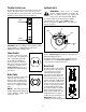
SECTION 1: IMPORTANT SAFE OPERATION PRACTICES WARNING: This symbol points out important safety instructions which, if not followed, could endanger the personal safety and/or property of yourself and others. Read and follow all instructions in this manual before attempting to operate this machine. Failure to comply with these instructions may result in personal injury. When you see this symbol—heed its warning.
. Follow the manufacturer’s recommendations for wheel weights or counterweights to improve stability. 5. Use extra care with grass catchers or other attachments. These can change the stability of the machine. 6. Keep all movement on the slopes slow and gradual. Do not make sudden changes in speed or direction. Rapid engagement or braking could cause the front of the machine to lift and rapidly flip over backwards which could cause serious injury. 7. Avoid starting or stopping on a slope.
e. Extinguish all cigarettes, cigars, pipes and other sources of ignition. f. Never fuel machine indoors. g. Never remove gas cap or add fuel while the engine is hot or running. Allow engine to cool at least two minutes before refueling. h. Never over fill fuel tank. Fill tank to no more than three inches below the top of the filler neck to allow space for fuel expansion. i. Replace gasoline cap and tighten securely. j. If gasoline is spilled, wipe it off the engine and equipment. Move unit to another area.
13. Observe proper disposal laws and regulations for gas, oil, etc. to protect the environment. 14. Grass catcher components and the discharge cover are subject to wear and damage which could expose moving parts or allow objects to be thrown. For safety protection, frequently check components and replace immediately with original equipment manufacturer’s (O.E.M.) parts only, listed in this manual.
SECTION 2: SLOPE GAUGE FOL D REP R E S ENT ING A 1 5 ° SL OPE OR A FENCE POST A CORNER OF A BUILDING A POWER POLE SIGHT AND HOLD THIS LEVEL WITH A VERTICAL TREE ON D OTT E D LINE , 15° WARNING Do not mow on inclines with a slope in excess of 15 degrees (a rise of approximately 2-1/2 feet every 10 feet). A riding mower could overturn and cause serious injury.
SECTION 3: TRACTOR SET-UP Attaching the Battery Cables IMPORTANT: Your tractor is shipped with oil in the engine. However, you MUST check the oil level before operating. Refer to Checking the Oil Level on page 19 for detailed instructions. Be careful not to overfill. The positive battery terminal is marked Pos. (+). The negative battery terminal is marked Neg. (–). • • • The positive cable (heavy red wire) is secured to the positive battery terminal (+) with a hex bolt and hex nut at the factory.
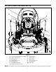
SECTION 4: KNOW YOUR LAWN TRACTOR A B G H C BRAKE I J D K L E F M NOTE: Steering Wheel not shown for clarity.
Throttle Control Lever Ignition Switch The throttle control lever is located on the left side of the tractor’s dash panel. This lever controls the speed of the engine. When set in a given position, the throttle will maintain a uniform engine speed. See Figure 4. WARNING: Never leave a running machine unattended. Always disengage the PTO, set parking brake, stop engine and remove key to prevent unintended starting.
Hour Meter Electric PTO (Power Take-off) Knob Located in the center of the tractor’s console, the hour meter operates whenever the engine is running and records the actual hours of tractor operation. See Figure 6. To engage the power to the cutting deck or other (separately available) attachments, pull outward on the PTO knob. Push the PTO knob inward to disengage the power to the cutting deck.
Seat Adjustment Lever Deck Lift Lever To adjust the seat forward or backward, slide the seat adjustment lever to the left and reposition the seat to the desired position. Once a comfortable position is found, release the seat adjustment lever to lock the seat in place. Refer to Seat Adjustment on page 17 of this manual for more detailed instructions. Found on your tractor’s right fender, the deck lift lever is used to change the height of the cutting deck.
• Lock nut After the engine starts, allow the engine to warm up by running it for 3 to 5 minutes at mid throttle before putting the equipment under load. NOTE: Do NOT operate the tractor with the choke Shoulder Screws control in any position other than fully depressed (choke open). Doing so will result in a "rich" fuel mixture and cause the engine to run poorly. Stopping the Engine WARNING: If you strike a foreign object, stop the engine, disconnect the spark plug wires and ground against the engine.
• • Setting The Cruise Control Briefly depress the brake pedal to release the parking brake. Move the throttle lever into the FAST (rabbit) position. To travel FORWARD, slowly depress the upper portion of the drive pedal forward until the desired speed is achieved. See Figure 8. NOTE: The cruise control feature should only be utilized while traveling in the forward direction. • Brake Pedal • • • Slowly depress the upper portion of the drive pedal until the desired speed is achieved.
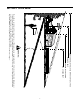
Moving The Tractor Manually Front View Your tractor’s transmission is equipped with a hydrostatic relief valve for occasions when it is necessary to move the tractor manually. Opening this valve permits the fluid in the transmission to bypass its normal route, allowing the rear tires to "freewheel." To engage the hydrostatic relief valve, proceed as follows: • Pull Out ON Push In OFF Locate the hydrostatic bypass rod in the rear of the tractor. See Figure 9.
Mulching Carriage Screw Model 1525 & 1527 lawn tractors come equipped with a mulch kit which incorporates special blades, already standard on your tractor, in a process of recirculating grass clippings repeatedly beneath the cutting deck. The ultra-fine clippings are then blown back into the lawn where they act as a natural fertilizer. Observe the following points for the best results when mulching. • • • • Never attempt to mulch if the lawn is damp.
Leveling the Deck necessary as follows: • With the tractor parked on a firm, level surface, place the deck lift lever in the top notch (highest position) and rotate both blades so that they are perpendicular to the tractor frame. • Measure the distance from the outside left blade tip to the ground and the distance from the outside right blade tip to the ground. The measurements should be equal. If they’re not, proceed to the next step.
• Looking at the transmission from the right side of the tractor, locate the compression spring and brake disc. See Figure 14. Hex Nut and Lock Washer Brake Rod Pivot Bar Axle Crown Nut Brake Disc Jam Nut Ball Joint Figure 15 NOTE: View shown from beneath tractor. NOTE: Threading the ball joints too far onto the drag links will cause the front tires to "toe-in" too far. Proper toe-in is between 1/16" and 5/16".
SECTION 7: MAINTAINING YOUR LAWN TRACTOR NOTE: Refer to Maintenance Chart on page 29 for a • reference of recommended maintenance intervals. WARNING: Before performing any maintenance or repairs, disengage PTO, set parking brake, stop engine and remove key to prevent unintended starting. • • Engine Maintenance, repair, or replacement of the emission control devices and systems, which are being done at the customer’s expense, may be performed by any engine repair establishment or individual.
• • Fill the crankcase until the oil level reaches the full (F) mark on the dipstick. Refer to Figure 16. Refer to the viscosity oil chart earlier in this section for information regarding the proper type of oil to add to the crankcase. • Grasp the side panel just behind the grille and pull outward to release the side panel from the tapered bushings on the grille. Slide the side panel forward and out of the groove in the dash panel. IMPORTANT: The oil capacity (with oil filter) is 1.8 U.S.
• • • • • check for loose or damaged components. Replace all damaged air cleaner components. Before removing the old oil filter, clean around its base to prevent debris from entering the crankcase. Grasp the oil filter and remove it from the engine by turning it counterclockwise. Use an oil filter wrench, if necessary. Place a new replacement filter in a shallow pan with the open end up and pour new oil of the proper type (see chart on page 19), in through the threaded center hole.
Spark Plug Service the Foam Precleaner • • • Clean the precleaner after every 25 hours of operation. More often if operating under extremely dusty or dirty conditions. Wash the precleaner in detergent and water. Rinse the precleaner thoroughly until all traces of detergent are eliminated. Squeeze out excess water — DO NOT WRING. Allow the foam element to air dry. Every 100 hours of operation, remove each spark plug, check its condition, and reset the gap or replace with a new plug as necessary.
Fuel Filter and Pump WARNING: Do not replace the fuel filter or pump when engine is hot. Grease Fitting The engine is equipped with an inline fuel filter and fuel pump located on the right side of the engine. Visually inspect the filter periodically for a build-up of residue inside the filter body, and for a dirty element which can be indicated by discoloration. Replace the fuel filter when dirty. The fuel pump can not be disassembled. If the fuel pump fails, replace it with a new one.
SECTION 8: SERVICE Head Lamp Uneven tire pressure could cause the cutting deck to mow unevenly. WARNING: If the engine has been recently Cutting Blades run, the engine, muffler and surrounding metal surfaces will be hot and can cause burns to the skin. Allow the tractor to cool and use caution when changing the lamp bulbs.
• If the cutting edge of the blade has already been sharpened to within 5/8" of the wind wing radius, or if any metal separation is present, replace the blades with new ones. See Figure 25. Wind Wing • Blade Separation Connect the second cable (negative –) to the other post of the jumper battery. Make the final connection on the engine block of the stalled tractor, away from the battery. Attach to a unpainted part to assure a good connection.
• Changing the Deck Belt(s) Looking at the cutting deck from the left side of the tractor, locate the deck support pin on the rear left side of the deck. Refer to Figure 26. WARNING: Be sure to shut the engine off, remove ignition key, and disconnect the spark plug wires to prevent unintended starting before removing the belts. Support Pin All belts on your tractor are subject to wear and should be replaced if any signs of wear are present.
PTO Idler Bracket (mounted on tractor) Electric PTO Clutch Belt Guard Model 1527 Deck belt (Bottom) Left Hand Pulley NOTE: Left hand belt PTO belt (Top) cover removed for clarity Right Hand Pulley (beneath belt guard) Deck Idler Pulley Double Pulley Self-Tapping Screws Figure 28 Model 1527 Changing The Transmission Drive Belt • All belts on your tractor are subject to wear and should be replaced if any signs of wear are present.
• • • • • • • Pivot the double-idler bracket to relieve as much spring tension as possible, then unhook the idler extension spring from the screw and the idler bracket itself. Do not misplace the spring. Slide the drive belt out and off of the pulleys on the double-idler bracket. Carefully unplug the tractor’s wire harness from the connector on the electric PTO clutch. Note the orientation of the electric PTO clutch.
SECTION 9: OFF-SEASON STORAGE Clean and lubricate the tractor as instructed in Section 7: MAINTAINING YOUR LAWN TRACTOR before storing for an extended period. Figure 30), use a phillips screwdriver to loosen the bowl drain screw and drain the bowl. Engine Phillips Screwdriver If the engine will be out of service for 30 days or more, the fuel system must be completely emptied, or the gasoline must be treated with a fuel stabilizer to prevent deterioration.
SECTION 11: TROUBLESHOOTING Trouble Possible Cause(s) Corrective Action Engine fails to start PTO knob engaged. Parking brake not engaged. Spark plug wire(s) disconnected. Throttle control lever not in correct starting position. Choke not activated Fuel tank empty, or stale fuel. Blocked fuel line. Faulty spark plug. Engine flooded. Unit running with CHOKE applied. Spark plug wire loose. Blocked fuel line or stale fuel. Place knob in disengaged (OFF) position. Engage parking brake.
SECTION 12: SPECIFICATIONS 1525 1527 3 gallons (11.4 liters) 3 gallons (11.4 liters) Capacities Fuel Tank Crankcase (approximately) 1.8 quarts / 57.6 oz. (1.7 liters) 1.8 quarts / 57.6 oz. (1.7 liters) 4.9 pints / 78.8 oz. (2.3 liters) 4.9 pints / 78.8 oz. (2.3 liters) Hydro-Gear 311-0710 Hydro-Gear 311-0710 22.2:1 22.2:1 Forward Speed 0 m.p.h. - 5.5 m.p.h. 0 m.p.h. - 5.5 m.p.h. Reverse Speed 0 m.p.h. - 2.5 m.p.h. 0 m.p.h. - 2.5 m.p.h.
SECTION 13: ATTACHMENTS & ACCESSORIES The following attachments and accessories are compatible for Model 1525 & Model 1527. See your Cub Cadet dealer or the retailer from which you purchased your tractor for information regarding price and availability. NOTE: Cub Cadet lawn tractor models 1525 and 1527 are NOT designed for use with any type of groundengaging attachments (e.g. tiller or mulboard plow). Use of this type of equipment WILL void the tractor’s warranty.
KAWASAKI LIMITED WARRANTY CALIFORNIA AND FEDERAL EMISSIONS CONTROL SYSTEMS SMALL OFF-ROAD ENGINES The California Air Resources Board, the Environmental Protection Agency (EPA) , and Kawasaki Motors Corp., U.S.A. (hereinafter “Kawasaki”) are pleased to explain the Emission Control Systems Warranty on your Kawasaki small off-road engine. In California and other states, new small off-road engines must be designed, built and equipped to meet the stringent anti-smog standards.
3. LIMITED LIABILITY. (a) The liability of Kawasaki under this Emission Control Systems Warranty is limited solely to the remedying of defects in materials or workmanship by any authorized Kawasaki small off-road engine dealer at its place of business during customary business hours. This warranty does not cover inconvenience or loss of use of the small off-road engine or transportation of the small off-road engine to or from the Kawasaki dealer.
CUB CADET LLC MANUFACTURER’S ONE YEAR LIMITED WARRANTY (COMMERCIAL USE) The limited warranty set forth below is given by CUB CADET LLC (“CUB CADET”) with respect to new merchandise purchased and used in the United States, its possessions and territories.
CUB CADET LLC MANUFACTURER’S LIMITED WARRANTY (RESIDENTIAL USE) The limited warranty set forth below is given by CUB CADET LLC (“CUB CADET”) with respect to new merchandise purchased and used in the United States, its possessions and territories.