Operator's Manual 1 Hydrostatic Lawn Tractor Models 1525 1527 IMPORTANT: READ SAFETY RULES AND INSTRUCTIONS CAREFULLY Warning: This unit is equipped with an internal combustion engine and should not be used on or near any unimproved forest-covered, brush-covered or grass-covered land unless the engine's exhaust system is equipped with a spark attester meeting applicable local or state Iaws (if any). If a spark attester is used, it should be maintained in effective working order by the operator.
TABLEOFCONTENTS Content Page Important Safe Operation Practices ............................................................................... 3 Slope Gauge .................................................................................................................. 7 Tractor Set-up ................................................................................................................ 8 Know Your Lawn Tractor ............................................................................
SECTION1: IMPORTANT SAFEOPERATION PRACTICES WARNING: This symbol points out important safety instructions which, if not followed, could endanger the personal safety and/or property of yourself and others. Read and follow all instructions in this manual before attempting to operate this machine. Failure to comply with these instructions may result in personal injury. When you see this symbol--heed its warning.
23. Mufflerandenginebecomehotandcancausea burn.Donottouch. 24. Checkoverhead clearances carefullybeforedriving underlowhangingtreebranches, wires,door openingsetc.,wheretheoperatormaybestruckor pulledfromtheunit,whichcouldresultinserious injury, 25. Disengage allattachment clutches,depressthe brakepedalcompletely beforeattempting tostart engine. 26. Yourmachineisdesignedtocutnormalresidential grassofa heightnomorethan10".Donotattempt tomowthroughunusually tall,drygrass(e.g., pasture)orpilesofdryleaves.
e. f. g. Use extreme care when approaching blind corners, doorways, shrubs, trees or other objects that may block your vision of a child who may run into the machine. Disengage the cutting blade(s) before traveling in reverse. The "No-Cut-In Reverse" feature is a reminder not to cut in reverse and e. f. g. Never remove gas cap oradd fuel while the engine is hot or running. Allow engine to cool at least two minutes before refueling. h. Never over fill fuel tank.
8. Nevertamperwiththesafetyinterlocksystemor othersafetydevices.Checktheirproperoperation regularly. 9. Afterstrikinga foreignobject,stoptheengine, disconnect thesparkplugwire(s)andground againsttheengine.Thoroughly inspectthe machineforanydamage.Repairthedamage beforestartingandoperating. 10. Neverattemptto makeadjustments or repairsto themachine whiletheengineis running. 11. Donotchangetheenginegovernorsettingsor over-speed theengine.Thegovernorcontrolsthe maximumsafeoperating speedoftheengine. 12.
SIGHT AND HOLD THIS LEVEL WITH A VERTICAL TREE A POWER POLE I uq A CORNER OF A BUILDING I '_-- "'-'._OLo o^, _ , ,, ,,,, , v/.90-,.... OR A FENCE POST , o, WARNING Do not mow on inclines with a slope in excess of 15 degrees (a rise of approximately 2-1/2 feet every 10 feet). A riding mower could overturn and cause serious injury. If operating a walk-behind mower on such a slope, it is extremely difficult to maintain your footing and you could slip, resulting in serious injury.
SECTION3: TRACTORSET-UP AttachingtheBatteryCables The positive battery terminal is marked Pos. (+). The negative battery terminal is marked Neg. (-). The positive cable (heavy red wire) is secured to the positive battery terminal (+) with a hex bolt and hex nut at the factory. Make certain that the rubber boot covers the terminal to protect it from corrosion. Lift the tractor's hood and remove the hex bolt and wing nut from the negative cable (thick black wire).
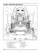
SECTION4: KNOWYOURLAWNTRACTOR A B C NOTE: Steering Wheel not shown for clarity. Figure 3 A B Systems Indicator Monitor/Hour Meter Throttle Control Lever H I Ignition Switch Brake Pedal C Choke Control J Drive Pedal D Parking Brake Lever K Cruise Control Lever E Fuel Tank Cap L Deck Lift Lever F Seat Adjustment Lever M Cup Holder G PTO (PowerTake-off) Knob NOTE: Any reference in this manual to the RIGHT or LEFT side of the tractor is observed from operator's position.
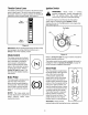
ThrottleControl Lever IgnitionSwitch The throttle control lever is located on the left side of the WARNING: Never leave a running machine unattended. Always disengage the PTO, set parking brake, stop engine and remove key to prevent unintended starting. tractor's dash panel. This lever controls the speed of the engine. When set in a given position, the throttle will maintain a uniform engine speed. See Figure 4.
HourMeter ElectricPTO Located in the center of the tractor's console, the hour meter operates whenever the engine is running and records the actual hours of tractor operation. See Figure 6. (PowerTake-off)Knob To engage the power to the cutting deck or other (separately available) attachments, pull outward on the PTO knob. Push the PTO knob inward to disengage the power to the cutting deck.
SeatAdJustment Lever DeckLiftLever To adjust the seat forward or backward, slide the seat adjustment lever to the left and reposition the seat to the desired position. Once a comfortable position is found, release the seat adjustment lever to lock the seat in place. Refer to SeatAdjustmenton page 17 of this manual for more detailed instructions. Found on your tractor's right fender, the deck lift lever is used to change the height of the cutting deck.
After the engine starts, allow the engine to warm up by running it for 3 to 5 minutes at mid throttle before putting the equipment under load. % Lock nut NOTE: Shoulder Screws Do NOT leave the choke control on while operating the tractor. Doing so will result in a "rich" fuel mixture and cause the engine to run poorly. Stoppingthe Engine WARNING: If you strike a foreign object, stop the engine, disconnect the spark plug wire(s) and ground against the engine.
Briefly depress the brake pedal to release the parking brake. Move the throttle lever into the FAST (rabbit) position. To travel FORWARD, slowly depress the upper portion of the drive pedal forward until the desired speed is achieved. See Figure 8. SettingTheCruiseControl NOTE: The cruise control feature should only be utilized while traveling in the forward direction. Slowly depress the upper portion of the drive pedal until the desired speed is achieved. Lightly depress the cruise control lever.
MovingTheTractorManually Front View Pull Out Your tractor's transmission is equipped with a hydrostatic relief valve for occasions when it is necessary to move the tractor manually. Opening this valve permits the fluid in the transmission to bypass its normal route, allowing the rear tires to "freewheel." To engage the hydrostatic relief valve, proceed as follows: Push In Locate the hydrostatic bypass rod in the rear of the tractor. See Figure 9.
Mulching Carriag, Model 1525 & 1527 lawn tractors come equipped with a mulch kit which incorporates special blades, already standard on your tractor, in a process of recirculating grass clippings repeatedly beneath the cutting deck. The ultra-fine clippings are then blown back into the lawn where they act as a natural fertilizer. Observe the following points for the best results when mulching. Never attempt to mulch if the lawn is damp.
With the tractor parked on a firm, level surface, place the deck lift lever in the top notch (highest position) and rotate both blades so that they are perpendicular with the tractor. LevelingtheDeck NOTE: Check the tractor's tire pressure before performing any deck leveling adjustments. Refer to Tires on page 24 for informafion regarding tire pressure. Measure the distance from the outside of the left blade tip to the ground and the distance from the outside of the right blade tip to the ground.
Looking at the transmission from the right side of the tractor, locate the compression spring and brake disc. See Figure 14. Brake Rod Hex Nut and Lock Washer Pivot Bar Jam Nut Ball Joint Figure 15 NOTE: View shown from beneath tractor. NOTE: Threading the ball joints too far onto the drag links will cause the front fires to "toe-in" too far. Proper toe-in is between 1/16" and 5/16". Figure 14 Carefully remove the cotter pin from the crown nut on the right side of the brake assembly.
SECTION7: MAINTAINING YOURLAWNTRACTOR Clean the area around the oil fill cap!dipstick to prevent debris from entering the crankcase. Refer to Figure 18. NOTE: Refer to MaintenanceChart on page 29 for a reference of recommended maintenance intervals. WARNING: Before performing any maintenance or repairs, disengage PTO, set parking brake, stop engine and remove key to prevent unintended starting. Remove the oil fill cap/dipstick by unthreading it (counterclockwise) and lifting it out of the oil fill tube.
Fill the crankcase until the oil level reaches the full Grasp the side panel just behind the grille and pull outward to release the side panel from the tapered bushings on the grille. Slide the side panel forward and out of the groove in the dash panel. (F) mark on the dipstick. Refer to Figure 16. Refer to the viscosity oil chart earlier in this section for information regarding the proper type of oil to add to the crankcase.
Before removing the old oil filter, clean around its base to prevent debris from entering the crankcase. Grasp the oil filter and remove it from the engine by turning it counterclockwise. Use an oil filter wrench, if necessary. Place a new replacement filter in a shallow pan with the open end up and pour new oil of the proper type (see chart on page 19), in through the threaded center hole. the air cleaner system. Keep this area clean. Also check for loose or damaged components.
Service the F0amPrecleaner Spark Plug Clean the precleaner after every 25 hours of operation. More often if operating under extremely dusty or dirty conditions. Wash the precleaner in detergent and water. Rinse the precleaner thoroughly until all traces of detergent are eliminated. Squeeze out excess water-- DO NOT WRING. Allow the foam element Every 100 hours of operation, remove the spark plug, check its condition, and reset the gap or replace with a new plug as necessary. NOTE: to air dry.
Fuel Filter and Pump _, pump when engine is hot. WARNING: Do not replace the fuel filter or The engine is equipped with an inline fuel filter and fuel pump located on the right side of the engine. Visually inspect the filter periodically for a build-up of residue inside the filter body, and for a dirty element which can be indicated by discoloration. Replace the fuel filter when dirty. The fuel pump can not be disassembled. pump fails, replace it with a new one.
SECTION8: SERVICE The recommended operating tire pressure is: approximately 10 psi for the rear tires and approximately 14 psi for the front tires. Refer to the tire sidewall for exact tire manufacturer's HeadLamp WARNING: If the engine has been recently run, the engine, muffler and surrounding metal surfaces will be hot and can cause burns to the skin. Allow the tractor to cool and use caution when changing the lamp bulbs. recommended or maximum psi. Do not overinflate.
To properly sharpen the cutting blades, remove equal amounts of metal from both ends of the blades along the cutting edges, parallel to the trailing edge, at a 25 ° to 30 ° angle.IMPORTANT: Make the final connection on the engine block of the stalled tractor, away from the battery. Attach to a unpainted part to assure a good connection. IMPORTANT: If the jumper battery is installed on a vehicle (i.e. car, truck), do NOT start the vehicle's engine when jump starting your tractor.
ChangingtheDeckBelt(s) Pin WARNING: Be sure to shut the engine off, remove ignition key, disconnect the spark plug wire(s) and ground against the engine to prevent unintended starting before removing the belt(s). All belts on your tractor are subject to wear and should be replaced if any signs of wear are present. IMPORTANT: The V-belts found on your tractor are specially designed to engage and disengage safely. A substitute (non-OEM) V-belt can be dangerous by not disengaging completely.
Electric PTO Clutch Model1527 PTO Idler Bracket (mounted on tractor) Left Hand Pulley • Deck belt (Bottom) • PTO belt (Top) Right Hand Pulley (beneath belt guard) Deck Idler Pulley Center Pulley Self-Tapping Screws NOTE: Left hand belt cover not shown for clarity. Figure 27 Remove the deck belt from around all pulleys, including the deck idler pulley. Route the new belts as shown in Figure 26 or Figure 27. Remount the belt guards removed earlier.
Remove the drive belt by feeding it from front to rear, toward the hydrostatic transmission. See Figure 28. Continue removing the drive belt by gently lifting it off of the transmission pulley and over the cooling fan. Reroute the new belt around the pulleys and belt keepers, if present, EXACTLY as the old one was routed. Refer to Figure 28. HydrostaticTransmission The hydrostatic transmission is sealed at the factory and is maintenance free. The fluid level cannot be checked nor can the oil be changed.
SECTION9: OFFmSEASON STORAGE Clean and lubricate the tractor as instructed in Section7: Figure 29), use a phillips screwdriver to loosen the bowl drain screw and drain the bowl. MAINTAINING YOURLAWNTRACTORbefore storing for an extended period. Phillips Engine / If the engine will be out of service for 30 days or more, the fuel system must be completely emptied, or the gasoline must be treated with a fuel stabilizer to prevent deterioration.
SECTION11: TROUBLESHOOTING Trouble Possible Engine fails to start PTO knob engaged. Parking brake not engaged. Spark plug wire(s) disconnected. Throttle control lever not in correct starting position. Choke not activated Fuel tank empty, or stale fuel. Blocked fuel line. Faulty spark plug. Engine flooded. Unit running with CHOKE applied. Spark plug wire loose. Blocked fuel line or stale fuel. Engine runs erratic Corrective Cause(s) Vent in gas cap plugged. Water or dirt in fuel system.
SECTION12: SPECIFICATIONS 1525 1527 3 gallons (11.4 liters) 3 gallons (11.4 liters) Capacities Fuel Tank 1.8 quarts / 57.6 oz. (1.7 liters) Crankcase (approximately) 4.9 pints / 78.8 oz. (2.3 liters) Transmission Case (approximately) Hydrostatic 1.8 quarts / 57.6 oz. (1.7 liters) 4.9 pints / 78.8 oz. (2.3 liters) Transmission Make and Model Hydro-Gear Gear Ratio 311-0710 Hydro-Gear 311-0710 22.2:1 22.2:1 Forward Speed 0 m.p,h. - 5.5 m.p.h. 0 m.p,h. - 5.5 m.p.h. Reverse Speed 0 m.p.h.
SECTION13: ATTACHMENTS& ACCESSORIES The following attachments and accessories are compatible for Model 1525 & Model 1527. See your Cub Cadet dealer or the retailer from which you purchased your tractor for information regarding price and availability. NOTE: Cub Cadet lawn tractor models 1525 and 1527 are NOT designed for use with any type of groundengaging attachments (e.g. tiller or mulboard plow). Use of this type of equipment WILL void the tractor's warranty.
KAWASAKI LIMITED WARRANTY CALIFORNIA AND FEDERAL EMISSIONS CONTROL SYSTEMS SMALL OFF-ROAD ENGINES The California Air Resources Board, the Environmental Protection Agency (EPA), and Kawasaki Motors Corp., U.S.A. (hereinafter "Kawasaki") are pleased to explain the Emission Control Systems Warranty on your Kawasaki small off-road engine. In California and other states, new small off-road engines must be designed, built and equipped to meet the stringent anti-smog standards.
3. LIMITED LIABILITY. (a) The liability of Kawasaki under this Emission Control Systems Warranty is limited solely to the remedying of defects in materials or workmanship by any authorized Kawasaki small off-road engine dealer at its place of business during customary business hours. This warranty does not cover inconvenience or loss of use of the small off-road engine or transportation of the small off-road engine to or from the Kawasaki dealer.
MANUFACTURER'S CUB CADET LLC ONE YEAR LIMITED WARRANTY (COMMERCIAL USE) The limited warranty set forth below is given by CUB CADET LLC ("CUB CADET") with respect to new merchandise purchased and used in the United States, its possessions and territories.
CUB CADET MANUFACTURER'S LLC LIMITED WARRANTY (RESIDENTIAL USE) The limited warranty set forth below is given by CUB CADET LLC ("CUB CADET") with respect to new merchandise purchased and used in the United States, its possessions and territories. CUB CADET warrants this product against defects in material and workmanship for a period of two (2) years for residential users, (one (1) year for commercial users), commencing on the date of original purchase and will, at its option, re_.