Operator's Manual 21-inch, 6-Speed Lawn Mower Model SC 621 IMPORTANT: Read safety rules and instructions carefully before operating equipment. Warning: This unit is equipped with an internal combustion engine and should not be used on or near any unimproved forestcovered, brush-covered or grass-covered land unless the engine's exhaust system is equipped with a spark attester meeting applicable local or state laws (if any).
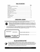
TABLEOFCONTENTS Content Page Important Safe Operation Practices ................................................................... 3 Slope Gauge ...................................................................................................... 6 Assembling Your Lawn Mower ........................................................................... 7 Know Your Lawn Mower .................................................................................... 9 Operating Your Lawn Mower ............
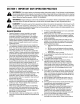
SECTION1: IMPORTANT SAFEOPERATION PRACTICES WARNING: This symbol points out important safety instructions which, if not followed, could endanger the personal safety and/or property of yourself and others. Read and follow all instructions in this manual before attempting to operate this machine. Failure to comply with these instructions may result in personal injury. When you see this symbol--HEED ITS WARNING.
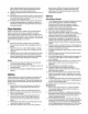
othersafety protective devices inplaceandworking. power mower. Children 14 years old and over should Never operate mower withdamaged safetydevices. read and understand the operation instructions and Failure todoso,canresultinpersonal injury. safety rules in this manual and should be trained and 21. Mufflerandenginebecomehotandcancauseabum. Do supervised by a parent. nottouch. 22. Onlyusepartsandaccessories made forthismachine by Service theodginal equipment manufacturer (O.E.M).
meettheoriginal equipment specifications mayleadto improper performance andcompromise safety!" 4. Mowerblades aresharpandcancut.Wrapthebladeor weargloves, anduseextra caution when servicing them. 5. 6. 7. 8. 9. Keep all nuts, bolts, and screws tight to be sure the equipment is in safe working condition. Never tamper with safety devices. Check their proper operation regularly. After striking a foreign object, stop the engine, disconnect the spark plug wire and ground against the engine.
USE THIS PAGE AS A GUIDE TO DETERMINE SLOPES WHERE YOU MAY NOT OPERATE SAFELY. ¢# SIGHT AND HOLD THIS LEVEL WITH A VERTICAL TREE A POWER POLE A CORNER OF A BUILDING OR A FENCE POST 5" I I O) ¢# o) ¢0 t I O3 ,.< O C 3 ¢0 o O ¢0 8. ¢# 3 o) ¢0 WARNING ,_ .'F Do not mow on inclines with a slope in excess of 15 degrees (a rise of approximately 2-1/2 feet every 10 feet). A riding mower could overturn and cause serious injury.
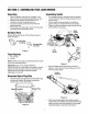
SECTION3: ASSEMBLING YOURLAWNMOWER Unpacking AssemblingHandle • • • • • Remove staples, break glue on top flaps, or cut tape at carton end and peel along top flap to open. Remove loose parts if included with unit (i.e., operator's manual, hardware pack etc.). Cut corners and lay carton down flat. Remove packing material. Roll or slide unit out of carton. Check for loose parts thoroughly before discarding carton. • • For shipping purposes, the grass bag was packed on top of the unit.
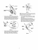
Cable Tie \ Lowe Handle Lowe_ Handl pin Clip Handle Mountin Bracket Figure 7 Figure 5 After you have moved the hairpin clips, place one carriage bolt (included in the hardware pack) in the upper hole of the right handle mounting bracket from the inside outward. See Figure 6. Secure with one plastic wing nut. Repeat process on the left. NOTE: Make sure the drive cable is routed around the outside and above the lower handle so as not to interfere with the grass bag attachment.
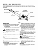
SECTION4: KNOWYOURLAWNMOWER Compare the illustrations in Figure 9 with your lawn mower to acquaint yourself with the location and working of various controls and adjustments on the equipment. Always wear safety glasses while performing any adjustments on the mower. Blade Control Cuffing Height _stment Lever Front Wheel Drive Clutch Control Front Wheel Height Adjuster Figure 9 Blade ControlHandle • The blade control handle is located on the upper handle of the mower.
SECTION5: OPERATING YOURLAWNMOWER rewind slowly. Pull rope with a rapid, continuous, full arm stroke. Keeping a firm grip on the starter handle, let the rope rewind slowly. GasandOilFill-Up • Service the engine with gasoline and oil as instructed in the accompanying engine manual. Follow all instructions carefully.
• To unlock caster: Lift and place the lock pin in the smaller hole to allow casters to rotate freely. See Figure 10. Chute Door Lift bag here Lower Handle of / Grass Bag / casters unlocked since the mower can drift WARNING: Do not mow on slopes with downhill. BaggingGrassClippings This mower can bag grass clippings. For that, you will have to install the grass bag on to the unit. • Remove the three wing nuts holding the mulching baffle or side discharge chute in place.
UsingYourRotaryMower • WARNING: If your mower strikes a foreign object, stop the engine. Remove wire from spark plug, thoroughly inspect for any damage, and do necessary repairs before operating the mower again. Extensive vibration of the mower during operation is an indication of damage. Make sure that lawn is clear of stones, sticks, wire, or other objects which could damage the lawn mower or its engine.. For best results, do not cut wet grass.
DriveClutchControl of the mower beside the engine. Follow steps below to adjust the shift lever. The drive clutch control adjustment wheel is located in the drive clutch control handle housing and is used to tighten or loosen the drive belt. You will have to adjust the drive clutch control if any of the following happens: 1. 2. • • • The mower does not propel itself with the drive clutch engaged. The mower's drive wheels hesitate with the drive • clutch engaged.
Lubrication WARNING: When removing the cutting blade for sharpening or replacement, protect hands by wearing heavy gloves or using a heavy rag to hold the blade. • • BladeControl • Remove the bolt and the blade bell support which hold the blade and the blade adapter to the engine crankshaft. See Figure 19 Remove the blade and the blade adapter from the crankshaft. See Figure 19. Lubricate the pivot points on the blade control handle and the brake cable at least once a season with light oil.
SECTION8: SERVICING YOURMOWER ReplacingDriveBelt • • • • • • Disconnect the spark plug wire and ground it against the engine. Drain the fuel tank or place a piece of plastic beneath the cap to prevent gasoline leakage. Place shift lever in the first position and tip the mower on its side. Remove the center bolt which secures the blade to Transmission __ Pulley Belt_ Belt Keepe Bracket-Idler Pulley --''''_ Bracket Idler_ Pulle_ the crankshaft followed by blade bell support, blade, and blade adapter.
Lower Pulley F o Lower Pulley Half'x / "_ _ o o o Belt ,_ Figure 27 Figure 25 • • • • • • Place the new belt over the transmission pulley. Start the belt in the pulley groove and rotate the pulley until the belt is seated in transmission pulley. Place the belt between the idler pulley and the belt keeper bracket. Using a pair of pliers, rotate the belt keeper bracket so that it snaps into slot on the idler bracket. Tighten the idler pulley bolt and lock nut half a turn.
SECTION10: TROUBLE SHOOTING GUIDE Trouble Possible Cause(s) 1. Blade control handle disengaged. 2. Spark plug wire disconnected. 3. Engine not primed. 4. Fuel tank empty, or stale fuel. 5. Blocked fuel line. 6. Faulty spark plug. 7. Engine flooded. 1. Spark plug wire loose. 2. Blocked fuel line or stale fuel. Corrective Action 3. 4. 5. 6. Vent in gas cap plugged. Water or dirt in fuel system. Dirty air cleaner. Carburetor out of adjustment. 3. 4. 5. 6. Engine overheats 1. 2. 3. 1. 2. 3.
SECTION11: PARTSLISTFORMODELSC621 Transmission Assembly 64 J 14 / 38 "_30 33 15 26 7 Pulley Assembly Reference only •75 6O 51 \ 58 55 59 56 \ 39 16 37 25 61 48 87 86 g 84 8 lO 83 /_ 70 68 18 NOTE: For painted parts, please refer to the list of color codes below. Please add the applicable color code wherever needed, to the pan number to order a replacement part. For instance if a part numbered 70O-xxxx is painted Cub Yellow. the part number to order would be 70Oxxxx-0716.
ModelSC621 Ref. No. I 2 3 4 5 6 7 8 9 10 11 12 13 14 15 16 17 18 19 20 21 22 23 24 25 26 27 28 29 30 31 32 33 34 35 36 37 38 39 40 41 42 Part No.
ModelSC621 27 16 24 \ A 23 \ \ \ 19 17 22 NOTE: For painted parts, please refer to [he list of color codes below. Please add the applicable color code wherever needed, to the par_ number to order a replacement parL For instance, if a part numbered 700-xxxx is painted Cub Yellow, the part number to order would be 700xxxx-0716. Cub Yellow: 0716 %wder Black: 0637 Ref. No. 1 2 3 4 5 6 8 11 12 14 16 17 18 19 20 21 22 23 Ref.
Multi-SpeedPulleyAssembly 15 13 Ref. No. 1 2 3 4 5 6 7 8 9 10 11 12 13 14 15 16 17 18 19 Part No. 746-0939 656-0613 710-0167 710-0896 711-1114 712-0287 732-0807 736-0270 736-0329 736-0526 738-0924 750-1070 750-1071 756-0625 782-7574A 782-7575A 782-7596 782-7597 712-0138 19 20 Description Speed Selector Cable, 53" Multi-Speed Pulley Assembly Carriage Bolt, 1/4-20 x. 5 Self-Tapping Screw, 1/4-20 x .625 Pivot Shaft Nut, 1/4-20 LH Torsion Spring Bell Washer, .265 x .75 x .
Transmission Assembly IMPORTANT: For a proper working machine, use Factory Approved Parts. V-BELTS are specially designed to engage and disengage safely. A substitute (non OEM_ V-Belt can be dangerous by not disengaging completely. Ref. No. 22 \ \ 27 32 31 \ 1 2 3 4 5 6 7 8 9 10 11 12 13 14 15 16 17 18 19 20 21 22 23 24 25 26 27 28 29 30 31 32 33 Part No.
Decorative& SafetyLabels 23
MANUFACTURER'S LIMITED WARRANTY TWO-YEAR RESIDENTIAL ONE-YEAR COMMERCIAL FOR: Proper maintenance of your Cub Cadet equipment is the owner's responsibility. Follow the instructions in your operator's manual for correct lubricants and maintenance schedule. Your Cub Cadet dealer carries a complete line of quality lubricants and filters for your equipment's engine, transmission, chassis and attachments.