® OPERATOR'S MANUAL 21" Self-Propelled Mower Model Number 379 IMPORTANT: READ SAFETY RULES AND INSTRUCTIONS CAREFULLY Warning: This unit is equipped with an internal combustion engine and should not be used on or near any unimproved forestcovered, brush-covered or grass-covered land unless the engine's exhaust system is equipped with a spark arrester meeting applicable local or state laws (if any). If a spark arrester is used, it should be maintained in effective working order by the operator.
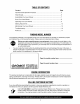
TABLEOFCONTENTS Content Page Important Safe Operation Practices ................................................................... 3 Slope Gauge ...................................................................................................... 6 Assembling Your Lawn Mower ........................................................................... 7 Know Your Lawn Mower .................................................................................... 8 Operating Your Lawn Mower ............
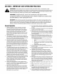
SECTION1: IMPORTANT SAFEOPERATION PRACTICES WARNING: This symbol points out important safety instructions which, if not followed, could endanger the personal safety and/or property of yourself and others. Read and follow all instructions in this manual before attempting to operate this machine. Failure to comply with these instructions may result in personal injury. When you see this symbol - heed its warning.
unclogging the chute. The cutting rotate for a few seconds Never place blade continues after the engine any part of the body in the blade area until you are sure the blade has stopped 20. Never operate discharge other mower cover, safety Never to is shut off. protective operate without grass catcher, mower devices proper trail shield, blade control safety to do so, can result in personal 21. Muffler and engine hot and can cause 22. not touch.
3. Check thebladeandengine mounting boltsatfrequent intervals forproper tightness. Also,visually inspect blade fordamage (e.g.,bent,cracked, worn)Replace blade withtheoriginal equipment manufacture's (O.E.M.) blade only,listedinthismanual. "Useofpartswhich donet meettheoriginal equipment specifications may lead to 4. 5. 6. 7. 8. improper performance and compromise safety!" Mower blades are sharp and can cut. Wrap the blade or wear gloves, and use extra caution when servicing them.
O SIGHT AND HOLD THIS LEVEL WITH A VERTICAL TREE E 1,91 A POWER POLE A CORNER OF A BUILDING O OR A FENCE POST o. O "5 o GI 03 O3 o_ ¢9 oO _5 C O3 E O ,.C o3 ¢9 o- 15 ° o . & 03 • WARNING Do not mow on inclines with a slope in excess of 15 degrees (a rise of approximately 2-1/2 feet every 10 feet). A riding mower could 03 O o.-_ .c o and you could slip, resulting in serious injury. overturn and cause seriousupinjury. If operating a walk-behind mower onslopes.
SECTION3: ASSEMBLING YOURLAWNMOWER IMPORTANT: This unit is shipped without gasoline or oil in the engine. Be certain to service engine with gasoline and oil as instructed in the separate engine manual before operating your mower. NOTE: Reference to right or left hand side of the mower is observed from the operating position. • Tighten the wing nuts and raise the handle assembly until it clicks into place. Make sure not to kink the control cables.
Handle Mountinq • • • Pinch Here Loosen the wing nut holding the rope guide to the upper handle. See Figure 6. Squeeze the blade control handle against the upper handle and pull starter rope out slowly. Thread the recoil starter rope into the rope guide and tighten the wing nut. Handle Hairpin Starter Rope Figure 4 Fasten the cables to the lower handle with the two cable ties found on the lower handle. Be sure to insert the post on the cable ties into the holes provided on the lower handle.
EngineControls Blade Control Handle_ See the separate engine manual for the location and function of the controls on the engine. Recoil Clutch Control Stopping Engine • Release blade control handle to stop the engine and the blade. • Disconnect spark plug wire and ground it to the post on the engine. ig Height Adjustment Lever Figure 7 SECTION5: OPERATING YOURLAWNMOWER TowardsBetterMowerPerformance 1. 2. 3. 4. Pour fresh, clean gasoline into the mower's gas tank until the tank is full.
• • • • Squeezethedriveclutchcontrolandpullthe mowerbackward.Dotherearwheelslock? Isthedriveclutchcontrolcablefreeofkinksor sharpbends? Ifyouanswered "yes"toallthreequestions, your mowerpassedthetestandyoucanstartyour mower. Ifyouanswered "no"toanyofthethreequestions, youwillhavetoadjustthedriveclutchcontrolas instructed intheADJUSTMENT SECTION. Mulching For effective mulching, do not cut wet grass because it tends to stick to the underside of the deck, preventing proper mulching of grass clippings.
Figure 11 AttachingSideDischarge(ifEquipped) Follow the steps below to install the side discharge chute: For the correct orientation see Figure 12. This side up Figure 9 AttachingMulchingPlug Follow the steps below to install the mulching plug: • Figure 12 For the correct orientation when installing see Figure 10. Raise the rear discharge door and remove the grass bag or mulch plug if installed. Hang the side discharge chute. See Figure 13.
SECTION6: MAKINGADJUSTMENTS Place the hairpin clips in the inner holes in the weld pins and insert the carriage bolts the upper hole on the handle mounting bracket and secure with plastic wing nuts. Reassemble the upper handle to the lower handle. Attach the starter rope as instructed in the Assembly Section. adjustments without engine WARNING: Do not atfirst any stopping time make any and disconnecting spark plug wire.
SECTION7: MAINTAININGYOURLAWNMOWER CustomerResponsibilities MAINTENANCE SCHEDULE I-O 8 no_ eeo _ _ q_ _ ._,A ,_ _ "ee _._.o_ ..,._o Lubricate Wheels ,_ Lubricate Blade Control ':_ Clean Deck '_ Blade Care Check Oil 4_ ,_ R_ Replace Air Filter Clean Engine SERVICE DATES q_ _ Change Oil _Z _ _,-_ 4_ _ uJ Check Spark Plug _ Check Spark Arrester (if any) GeneralRecommendations • • • • • • i_ least once a season with light oil. These handles must operate freely in both directions.
Maintenance speeds. It may cause damage to the mower, and could break causing personal injury. NOTE: When tipping the unit, empty the fuel tank and keep the air cleaner side of engine up. Never tip the mower more than 90 degrees and do not leave the mower tipped for any length of time. Oil can drain into the upper part of the engine causing a starting problem. Blade Adapter_ Engine Blade Bell Refer to the separate engine manual for all engine maintenance instructions.
Belt Keeper Hex Lock Nut Figure 21 NOTE: Mower is shown tipped on engine for clarity. Remember, only tip mower back on its handle with the spark plug facing up. Otherwise, oil will spill if tumed upside down. 6 is • • • • Figure 19 • Remove the blade, blade adapter and related hardware. See Figure 20. Remove the three hex head screws holding the small baffle and remove the small baffle. Remove the large baffle as well. mall • • Replace the large baffle. Refer to Figure 20.
SECTION8: TROUBLE SHOOTING GUIDE Problem Engine fails to start Engine runs erratic Cause Remedy 1. 2. 3. 4. Blade control handle disengaged. Spark plug wire disconnected. Fuel tank empty or stale fuel. Blocked fuel line. 1. 2. 3. 4. Engage blade control handle. Connect wire to spark plug. Fill tank with clean, fresh gasoline. Clean fuel line. 5. 6. Faulty spark plug. Engine flooded 5. 6. Clean, adjust gap, or replace. Wait a few minutes to start engine. 1. 2. Spark plug wire loose.
Model379 Front Axle Assembly Ref, No. 1. 2. 3. 4. 5. 6. 7. 8. 9. Part No. 611-9960 719-1348 714-9194 732-9820 747-9929A 736-9195 738-9192 734-2915A 731-9982A & Height Adjuster Description Axle Ass'y, Frt. AB Pan Scr. 1/4-14 x .50 Lg. Cotter Pin .072 x 1.12 Lg. Ext. Spring Adj. Rod Spr. Washer Shl. Bolt .498 x 1.445 3/8-16 Wheel Ass'y - Complete Hub Cap R_. No, 1. 2. 3. 4. 5. 6. 7. 8. 9. 10. 11. 12. 13. 14. 15. 16. 17. 18. 19. 20. 21. 22. 23. 24. 25. 26. 27. 28. 29. 30. 31. 32. 33. 17 Part No.
Model379 \ 125 \ 1 17 27 / 19 \ / / 62 57 _120 106 8,4 z132 24 '01 44 97 11 / 126 115 119 \ \ 114 118 / 81 18
Model379 Ref. No. 1. 2. 3. 4. 8. 6. 7. 8. 9. 12. 13. 14. 15. 16. 17. 18. 19. 20. 21. 22. 23. 24. 28. 28. 38. 37. 38. 39. 44. 48. 47. 48. 49. 52. 53. 56. 57. 58. 59. 61. 62. 72. 73. 74. 76. 76. 77. 78. 79. 80. 81. Part No.
MANUFACTURER'S LIMITED WARRANTY FOR: ® The limited warranty set forth below is given by Cub Cadet LLC with respect to new merchandise purchased and used in the United States, its possessions and territories. d. Cub Cadet LLC warrants this product against defects for a period of two (2) years commencing on the date of original purchase and will, at its option, repair or replace, free of charge, any part found to be defective in materials or workmanship.