OPERATOR’S MANUAL Automatic Transmission Garden Tractor Model 1212 IMPORTANT: READ SAFETY RULES AND INSTRUCTIONS CAREFULLY Warning: This unit is equipped with an internal combustion engine and should not be used on or near any unimproved forest-covered, brush-covered or grass-covered land unless the engine’s exhaust system is equipped with a spark arrester meeting applicable local or state laws (if any). If a spark arrester is used, it should be maintained in effective working order by the operator.
SECTION 1: TABLE OF CONTENTS PAGE FINDING YOUR MODEL NUMBER . . . . . . . . . . . . . . . . . . . . . . . . . . . . . . . . . . . . . . . . . . . . . . . . . . . . . . . 2 CALLING CUSTOMER SUPPORT. . . . . . . . . . . . . . . . . . . . . . . . . . . . . . . . . . . . . . . . . . . . . . . . . . . . . . . . 2 IMPORTANT SAFE OPERATION PRACTICES. . . . . . . . . . . . . . . . . . . . . . . . . . . . . . . . . . . . . . . . . . . . . . 3 SAFETY LABLES FOUND ON YOUR UNIT. . . . . . . . . . . . . . . . . . . . .
SECTION 4: IMPORTANT SAFE OPERATION PRACTICES WARNING: THIS SYMBOL POINTS OUT IMPORTANT SAFETY INSTRUCTIONS WHICH, IF NOT FOLLOWED, COULD ENDANGER THE PERSONAL SAFETY AND/OR PROPERTY OF YOURSELF AND OTHERS. READ AND FOLLOW ALL INSTRUCTIONS IN THIS MANUAL BEFORE ATTEMPTING TO OPERATE YOUR LAWN MOWER. FAILURE TO COMPLY WITH THESE INSTRUCTIONS MAY RESULT IN PERSONAL INJURY. WHEN YOU SEE THIS SYMBOL, HEED ITS WARNING.
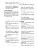
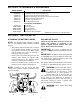
3. CHILDREN • Disengage all attachment clutches, thoroughly depress the brake pedal, and shift into neutral before attempting to start engine. Tragic accidents can occur if the operator is not alert to the presence of children. Children are often attracted to the machine and the mowing activity. Never assume that children will remain where you last saw them. • Your mower is designed to cut normal residential grass of a height no more than 10". Do not attempt to mow through unusually tall, dry grass (e.g.
• Keep all nuts, bolts and screws tight to be sure the equipment is in safe working condition. • Do not change the engine governor settings or overspeed the engine. Excessive engine speeds are dangerous. • Never tamper with safety devices. Check their proper operation regularly. Use all guards as instructed in this manual. • Observe proper disposal laws and regulations. Improper disposal of fluids and materials can harm the environment and the ecology.
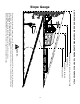
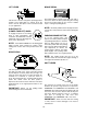
Slope Gauge ED LIN E , REP RE S E NTIN G A 15 ° SL OPE OR A FENCE POST A CORNER OF A BUILDING A POWER POLE SIGHT AND HOLD THIS LEVEL WITH A VERTICAL TREE USE THIS PAGE AS A GUIDE TO DETERMINE SLOPES WHERE YOU MAY NOT OPERATE SAFELY. FOL D ON D OTT 15° WARNING Do not mow on inclines with a slope in excess of 15 degrees (a rise of approximately 2-1/2 feet every 10 feet). A riding mower could overturn and cause serious injury.
SECTION 5: ATTACHMENTS & ACCESSORIES MODEL NUMBER OEM-190-118 190-603-101 190-604-101 190-821-101 190-822-101 190-823-101 190-824-101 DESCRIPTION Mulch Kit (For 46-inch Decks Only) Front Bumber Kit (Mounts On Front Of Tractor) Storage Container (Mounts On Rear Of Tractor) FastAttach Triple Bagger Grass Collector (For 46-inch Decks Only) FastAttach 46-inch Front Dozer Blade 42-inch Two-stage Snowthrower Sleeve Hitch with Electric Lift ™ ™ SLEEVE HITCH ATTACHMENTS 30-inch Tiller* Row Crop Cultivator* Single
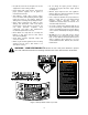
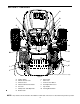
SECTION 7: CONTROLS D B F J A C + 1/10 P G H M E K I L NOTE: Steering Wheel not shown for clarity. Figure 3 A B C D E F G Ignition Switch Throttle Control Lever Choke Control Indicator Monitor/Hour Meter Lift Lever PTO (Power Take-Off) Knob Brake Pedal H I J K L M Drive Pedal Shift Lever Cruise Control Button Seat Adjustment Lever Cup Holder Parking Brake Button NOTE: Any reference in this manual to the RIGHT or LEFT side of the tractor is observed from operator’s position.
IGNITION SWITCH CHOKE CONTROL To start the engine, insert key into the ignition switch and turn clockwise to the START position. Release key to the ON position once engine has fired. See Figure 4. Refer to STARTING THE ENGINE in the OPERATION section of this manual for detailed starting instructions. The ignition switch is also used to operate the headlights.
LIFT LEVER BRAKE PEDAL BRAKE The brake pedal is located on the right front side of the tractor above the drive pedal along the running board. The brake pedal can be used for sudden stops or setting the parking brake. The lift lever is used to change the operating position (height) of the cutting deck. To operate, move the lever to the left, then place in the notch best suited for your application.
CRUISE CONTROL BUTTON SEAT ADJUSTMENT LEVER The cruise control button is located on the tractor dash panel to the left of the ignition switch. Push the cruise control button while traveling forward at a desired speed. WHILE HOLDING THE BUTTON IN, release pressure from the drive pedal. This will engage the cruise control and allow the tractor to remain at that speed without applying pressure to the drive pedal. Depress the brake pedal or the drive pedal to deactivate cruise control.
SETTING THE CUTTING HEIGHT NOTE: Do NOT leave the choke control out while Select the height position of the cutting deck by placing the deck lift lever in any of the six different cutting height notches on the right side of the fender. Then adjust the deck wheels, or rollers (on units equipped with a 50" deck) so that they are at least 1/4 inch to 1/2 inch above the ground when the tractor is on a smooth, flat surface such as a driveway. operating the tractor.
SETTING THE CRUISE CONTROL OPERATING THE HEADLIGHTS To turn the tractor’s headlights on: NOTE: The cruise control feature should only be • Start the engine following the instructions earlier in this section. utilized in the forward direction. • Move the shift lever into either the FORWARD—Hi or FORWARD—Lo position, then slowly depress the drive pedal until the desired speed is achieved. • Lightly push downward.
• Pull the PTO knob outward into the engaged (ON) position. See Figure 7. WARNING: Never direct the discharge of material toward bystanders or allow anyone near the machine while in operation. • Keep the throttle lever in the FAST (rabbit) position for the most efficient use of the cutting deck and other attachments. • For best results it is recommended that the first two laps should be cut with the discharge thrown towards the center.
• Loosen the two jam nuts on the rear side of the deck stabilizer bracket. See Figure 8A. • Locate the two lock nuts on the opposite side of the stabilizer bracket. See Figure 8A. Tighten the lock nuts to raise the front of the deck; loosen the lock nuts to lower the front of the deck. • Retighten the two jam nuts loosened earlier when proper adjustment is achieved. Side to Side If the cutting deck appears to be mowing unevenly, a side to side adjustment can be performed.
NOTE: Be certain that the left roller bracket and • Thread the ball joint toward the jam nut to shorten the drag link. Thread the ball joint away from the jam nut to lengthen the drag link. the right roller bracket are set in the same position. SEAT ADJUSTMENT • Replace hex nut and lock washer and retighten the jam nut after proper adjustment is achieved. To adjust the position of the seat, move the seat adjustment lever (located under the seat) to the left and slide the seat forward or backwards.
BRAKE ADJUSTMENT If the tractor does not come to a complete stop when the brake pedal is completely depressed, or if the tractor’s rear wheels can roll with the parking brake applied, the brake is in need of adjustment. The brake disc can be found on the right side of the transmission in the rear of the tractor. Adjust if necessary as follows: • Re-tighten the hex nut loosened earlier. Hex Nut • Looking at the brake disc from the right side of the tractor, locate the compression spring and brake disc.
CLEANING THE ENGINE AND DECK IMPORTANT: The use a pressure washer or Any fuel or oil spilled on the machine should be wiped off promptly. Do NOT allow grass, leaves, and dirt to accumulate around the cooling fins of the engine or on any other part of the machine, especially the pulleys and other moving parts. Clean the underside of the deck with a wisk broom, putty knife or forced air after each mowing. garden hose to clean your tractor is NOT recommended.
• Move the lift lever into the top notch on the right fender to raise the deck lift arms out of the way. • Gently slide the cutting deck (from the right side) out from underneath the tractor. NOTE: To properly remount the cutting deck, • Gently slide the cutting deck toward the front of the tractor allowing the hooks on the deck to release themselves from the deck stabilizer rod. Do NOT let the deck fall to the ground. perform the above steps in reverse order.
CHANGING THE TRANSMISSION DRIVE BELTS Variable-Speed Pulley Drive belt (Lower) Shift Lever Drive belt (Upper) Rear Idler Pulley Belt Keeper Battery Tray Opening Belt Keeper Front Idler Pulley Keeper Pins Double Idler Bracket Transmission Idler Pulley Engine Pulley Electric PTO Clutch Belt Keeper Idler Bracket Two-speed Transmission NOTE: Transmission Pulley View shown from above tractor.
Upper Drive Belt • Locate the transmission idler pulley on the upper drive belt by looking through the battery tray opening. See Figure 17. • Remove the rear idler pulley from the doubleidler bracket while unrouting the belt from around both the rear and the front idler pulley. Refer to Figure 17. • Pivot the transmission idler pulley toward the rear of the tractor to release tension on the upper drive belt. • Carefully unplug the tractor’s wire harness from the connector on the electric PTO clutch.
BATTERY The drive pedal is properly adjusted when the hole found in the double idler bracket has approximately 1-3/8" of travel with ten pounds of pressure applied to the drive pedal. See Figure 19. The battery is sealed and is maintenance-free. Acid levels cannot be checked. • Always keep the battery cables and terminals clean and free of corrosive build-up.
TIRES To properly sharpen the cutting blades, remove equal amounts of metal from both ends of the blades along the cutting edges. See Figure 23. Sharpen the cutting edge straight across, parallel to the trailing edge, at a 25° to 30° angle. See Figure 23. The recommended operating tire pressure is approximately 10 psi for the rear tires and 10 psi for the front tires. Refer to the tire sidewall for exact tire manufacturer’s recommended psi. Do not overinflate.
SECTION 11: LUBRICATION WARNING: Always stop the engine and disconnect the spark plug wire(s) and ground against the engine before performing any adjustments, repairs or maintenance. ENGINE Lubricate the engine with motor oil as instructed in the separate engine manual packed with your unit. PIVOT POINTS Lubricate all pivot points (drive pedal, brake pedal, etc.) at least once a season with light oil. STEERING SHAFT Lubricate the steering shaft at least once a season with light oil.
SECTION 12: TROUBLESHOOTING GUIDE Trouble Possible Cause(s) Corrective Action Engine will Safety switch not crank button not depressed. There are two safety switches in the starting circuit of your unit: the brake pedal switch and the seat switch. Make certain the actuator is fully depressing the button on the brake switch. The operator must be seated on the tractor in order to depress the seat switch. The PTO knob must be in the disengaged (OFF) positio in order to start the engine, also.
Model 1212 1 14 8 10 18/19 9 16 15 3 11 5 13 4 2 17 6 5 13 5 7 REF. PART NO. NO. 1 625-0051 2 629-0939 629-0941 3 629-0126 4 710-0599 5 712-3006 6 725-1426 7 725-1657A 8 725-1741 9 725-1743 10 725-1745 11 725-1747 12 736-0222 13 736-0329 14 629-0309 15 725-1752 16 783-0462 17 725-3007A 18 729-0357 19 725-1381 DESCRIPTION Bulb/Socket Headlight Assembly Wiring Harness w/o Ref. 14 (units w/ B&S Intek Twin) Wiring Harness w/o Ref.
C30 C85 C86 C87 C87 27 STARTER ALTERNATOR AFTERFIRE SOL ALTERNATOR MAGNETO HEADLIGHTS ELECTRIC PTO ELECTRIC PTO GREEN RELAY:725-1718 GREEN YELLOW/BLACK RED WHITE/BLACK WHITE - BLUE GREEN WHITE BATTERY RED RED/BLACK RED WHITE YELLOW WHITE/BLACK BLUE/WHITE + RELAY 725-1648 RED ORANGE/WHITE GREEN SOLENOID 725-1426 YELLOW ORANGE RED KEY SWITCH 725-1741 FUSE 725-1381 BRAKE SWITCH 725-1657A PTO SWITCH 725-1716 L M A1 A2 RED B S G YELLOW/BLACK ORANGE/BLACK YELLOW/WHITE OR
Model 1212 45 20 46 47 30 29 28 5 40 31 37 26 33 34 38 27 32 16 41 35 21 2 24 36 9 17 12 25 23 42 6 10 15 12 14 23 23 44 19 13 11 7 43 4 3 5 12 28
Tractor Body REF. NO. 1 2 3 4 5 6 7 8 9 10 11 12 13 14 15 16 17 18 19 20 21 22 23 24 PART NO. 683-0195 710-0599 710-0751 710-0924 710-1017 710-1268 710-3008 712-0271 712-0292 712-0431 726-0211 726-0293 731-1854 735-0126 736-0105 746-1085 783-0475 783-0476A 783-0477 783-0478A 783-0551 783-0553A 710-0604A 751-0603 DESCRIPTION Bracket Assembly (8-style) Self-tapping Screw, 1/4-20 x .5 Hex Cap Screw, 1/4-20 x .62 Phillips Pan Screw, 1/4-20 x .75 Truss Phillips Screw, 1/4-20 x .625 Screw, #10-16 x .
Model 1212 49 43 42 39 46 45 41 37 48 44 30 6 34 45 36 47 16 38 28 35 32 31 28 29 54 55 52 11 27 33 29 53 50 51 6 14 2 13 9 8 14 18 5 19 8 12 17 21 22 10 20 6 23 25 19 21 22 24 6 14 8 3 16 1 4 5 4 15 26 30 17 16 9 7
Lift Assembly REF. NO. 1 2 3 4 5 6 7 8 9 10 11 12 13 14 15 16 17 18 19 20 21 22 23 24 25 26 27 28 PART NO. 747-1130 683-0197 711-0332 712-0206 712-0431 712-3004A 712-3083 714-0104 714-0111 716-0106 720-0311 732-0874 732-0934 736-0275 736-0921 736-3019 736-3084 738-0138 738-0380 741-0225 741-0715 746-0968 747-1111 756-1154 783-0678 783-0720A 710-0260 710-0604 REF. NO. 29 30 31 32 33 34 35 36 37 38 39 40 41 42 43 44 45 46 47 48 49 50 51 DESCRIPTION Deck Stabilizer Rod Lift Shaft Assembly Clevis Pin, .5 x .
Model 1212 24 43 42 23 19 6 38 21 14 20 4 2 20 13 22 11 18 7 13 22 8 30 13 15 12 42 41 5 28 1 32 10 17 37 11 3 2 35 30 2 32 27 35 39 40 34 32 31 33 37 36 29 32 29 33 31 9 16 26 25
Steering Assembly REF. NO. 1 2 3 4 5 6 7 8 9 10 11 12 13 14 15 16 17 18 19 20 21 22 23 PART NO. 683-0304 710-0604A 783-0726A 783-0727 783-0728 710-0514 711-1409 711-1408 712-0240 712-0241 712-0431 712-0459 712-3004A 717-1550A 717-1554 723-0448A 736-0169 736-3084 738-1001A 741-0475 741-0656 738-0372 731-2295 REF. NO. 24 25 26 27 28 29 30 31 32 33 34 35 36 DESCRIPTION Lower Frame Assembly Self-tapping Screw, 16-18 x .
Model 1212 8 13 30 24 25 3 85 4 13 21 84 73 18 16 28 32 74 13 8 26 9 80 17 31 5 42 12 23 37 10 6 52 51 55 42 18 34 1 52 60 63 60 50 66 65 68 7 52 40 36 33 43 72 67 48 13 47 45 18 29 19 71 80 14 13 57 70 75 20 52 58 54 22 57 64 56 59 20 30 61 53 63 57 22 20 46 49 64 35 83 22 13 81 12 76 77 18 2 20 13 82 35 20 27 11 13 15 78 34
Drive System REF. NO. 1 2 3 4 5 6 7 8 9 10 11 12 13 14 15 16 17 18 19 20 21 22 23 24 25 26 27 28 29 30 31 32 33 34 35 36 37 38 39 40 41 42 43 44 PART NO.
Model 1212 48 44* 47 11 49 34 18 37 9 40 12 46 43 42 23 29 15 28 36 41 31 10 5 7 14 31 13 2 27 4 35 25 17 22 26 8 38 36 16 12 20 9 36 19 6 24 3 32 21 18 30 1 33 4 15 36
Two-speed Transmission REF. NO. 1 2 3 4 5 6 7 8 9 10 11 12 13 14 15 16 17 18 19 20 21 22 23 24 25 26 27 28 29 30 31 32 33 34 35 36 37 38 39 40 41 42 43 44 46 47 48 49 PART NO.
Model 1212 43 2 1 2 3 4 42 13 10 14 15 17 16 5 12 11 5 6 7 8 27 18 20 19 6 40 9 28 39 16 26 41 23 24 25 1 21 1 22 29 28 30 31 38 32 33 37 34 36 35 38
Power Take-off Systems REF. NO. 1 2 3 4 5 6 7 8 9 10 11 12 13 14 15 16 17 18 19 20 21 22 PART NO. 712-0431 732-0735 783-0733 732-0956 710-0604A 710-0751 712-0271 712-3044 725-1706 738-1014 738-1020 736-0407 723-0444 783-1033 725-1747 736-0222 725-1426 710-0599 712-0459 683-0304 756-0639A 783-1003 REF. NO. 23 24 25 26 27 28 29 30 31 32 33 34 35 36 37 38 DESCRIPTION Flange Lock Nut, 3/8-16 Compression Spring, 1.318 x 2.37 Spacer Cup, 1.5 OD Compression Spring, .66 OD x 1.5 Self-tapping Screw, 5/16-18 x .
Model 1212 10 10 3 38 18 10 33 14 16 24 34 10 18 2 28 35 39 7 42 3 29 9 27 25 21 20 26 18 32 19 19 5 23 22 13 23 32 36 19 15 19 18 1 18 29 25 26 8 12 26 41 37 6 11 1 31 40 30 17 30 17 40
46-inch Cutting Deck REF. NO. 1 2 3 4 5 6 7 8 9 10 11 12 13 14 15 16 17 18 19 20 21 PART NO. 17982 618-0430 618-0431 683-0254 683-0199B 710-0167 710-0347 710-0514 710-0528 710-0599 710-0650 710-0751 710-1260A 712-0106 16606 712-0291 712-0417A 712-0431 712-3027 714-0104 717-1553A DESCRIPTION Reinforcement Spindle Plate Center Spindle Assembly, 5 Dia. Double Pulley Spindle Assembly Deck Adjustment Bracket w/ Weld Nut 46-inch Deck Shell Carriage Screw, 1/4-20 x .5 Hex Cap Screw, 3/8-16 x 1.
Engine Accessories Model 1212 9 24 Briggs & Stratton Intek Twin 11 (for choke) 7 13 9 22 3 23 (for throttle) 4 2 12 19 20 18 21 6 8 10 5 10 5 16 15 REF. NO. 1 2 3 4 5 6 7 8 9 10 11 12 13 14 15 16 17 18 19 20 21 22 23 24 PART NO. 710-0148 710-0599 710-0604A 710-1237 710-1314 710-1315 712-3017 721-0460 726-0205 736-0119 736-0300 751B221535 751-0535 751-0564 751-0616 751-0650 751-0651 751-3140 751-3141-12 751-3142 783-0615 783-0625B 746-1086 722-0263 DESCRIPTION Self Tapping Screw, #8-32 x .
Labels Model 1212 43
MANUFACTURER’S LIMITED WARRANTY FOR: The limited warranty set forth below is given by Cub Cadet Corp. with respect to new merchandise purchased and used in the United States, its possessions and territories. Cub Cadet Corp. warrants this product against defects in material and workmanship for a period of two (2) years commencing on the date of original purchase and will, at its option, repair or replace, free of charge, any part found to be defective in material or workmanship.