Cub Camel” Owner’s Manual Important: Read Safety Rules and Instructions Carefully Thank you for purchasing an American-built product. GEAR DRIVE HOME TRACTORS Model Numbers 805 (192) 1105 (292) 1605 (392) CUB CADET CORPORATION = P.O. BOX 36930 « CLEVELAND, OHIO 44136 PRINTED IN U.S.A. FORM NO.
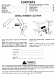
CONTENTS Serial No. Location . 2 Safe Operations . . Contrails . Operation . Adjustments . Maintenance Off-Season Storage Serial number plate is located on left hand side frame. NOTE: LEFT and RIGHT indicate the left and right sides of the tractor when facing forward in the driver's seat. Reference to FRONT indicates the grille end of the tractor; to REAR the draw bar end. CHASSIS S/N ENGINE S/N MODEL Mowing Deck—Adjustment and Operation Attaching Mower to Tractor .
WORK THESE RULES Instructions given with this symbol are for personal safety. Be sure you and your workers follow them. A CAREFUL OPERATOR iS THE BEST INSURANCE AGAINST AN ACCIDENT . Read this owner's manual carefully in its entirety before attempting to assemble or operate this unit. Keep this manual in a safe place for future and regular reference. . This unit is a precision piece of power equipment, not a plaything. Therefore exercise extremes caution at all times. .
29. 30. Never store the equipment with fuel in the tank inside a bulling where fumes may reach an open flame or spark. Allow engine to coif therefor storing in any enclosure. To reduce fire hazard, keep engine free of grass, leaves or excessive grease. blade comes to a complete stop before removing the grass catcher. (4) Check blade mounting bolts for proper tightness at frequent intervals, 34. Look behind to make sure the area is clear therefor placing the transmission in reverse 31.
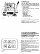
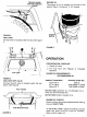
FIGURE 1. FIGURE 2. 1 RETIHMMOO® > CONTROLS Your Cub Cadet Tractor has been safety engineered. Thoroughly acquaint yourself with all the instruments and controls before attempting to start or operate the tractor. . Charge Indicator . Electronic Monitor (11 and 16 H.P, Units Only) . Ignition Switch . Lift Control Lever . Power Take-Off (PTO) Parking Brake Lever . Choke Control . Brake Pedal Clutch Pedal . Throttle Control Lever . Light Switch (16 H.P. Only) A.
€. IGNITION SWITCH The ignition switch is a three position switch. Turn key 1o “START" position when engine starts, then release key. Key will retract to “ON” position. Turn key to “OFF" position to stop engine. See figure 1. B TEE Remove the key from the tractor when the tractor is not in use o prevent accidental starting and battery discharge. D. LIFT CONTROL LEVER This control lever is used to raise and lower the cutting deck and other attachments. See figure 1. E.
Reverse Switch and PTO Indicator FIGURE 4. FUEL TANK The fuel tank is located under the seat. See figure Fuel Tank FIGURE 5. FUEL SHUT-OFF VALVE The fuel shut-off valve is located under the rear fender. See figure 6. Rear Fender FIGURE 6. ENGINE OIL The engine oil fill is located on the side of the engine. Figure 7 shows an 11 H.P. engine. Engine Oil Fill FIGURE 7. OPERATION PER-OPERATION CHECKLIST 1. Check Qil Level 2.
H.P. Units— Remove oil fill plug. Be certain oil level is maintained full to the point of overflowing. BEFORE OPERATING YOUR TRACTOR 1. Before you operate the tractor, study this manual carefully. It has been prepared to help you operate and maintain your tractor with utmost efficiency. 2. Familiarize yourself with the operation of all the instruments and controls. 3. Fill the fuel tank with clean, fresh, regular or unleaded gasoline. See figure 8. Tank is located under the seat. Nfig FIGURE 8.
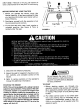
3. Move throttle contra forward to start position {never start engine at full throttler. 4. Turin key to start position. When engine starts, release key. Key will retract to on position, TO SHUT OFF 1. Return gear shift lever to neutral, engage parking brake and return PTO to off position, 2. Move throttle to slow position. 3. Turn key to off position and remove. CAUTION During operation do not run the engine in confined area such as storage building. Immediately move the tractor outside of the building.
Always be sure the rear wheels are free to turn, Under any adverse conditions, do not attempt to free the tractor by speeding up the engine and suddenly moving gear shift lever to extreme forward or reverse position. Try backing out instead of going forward. Do not leave the seat of the tractor without locking the parking brake. if leaving the tractor unattended, stop engine by moving throttle to slow position. Turn the ignition key off and remove the key.
Seat Adjustment Bol FIGURE 12. FRAME COVER REMOVAL To remove the frame cover, the seat assembly must be removed. 1. Remove two screws from one seat bracket. Slide seat assembly off the pin on the other seat bracket. 2. Remove screw and flat washer from frame cover as shown in figure 12. 3. Remove two screws holding frame cover to frame in the step through area (not shown). 4. Disconnect seat switch to harness. 5. Lift up and slide frame cover rearward from underneath the pedestal. 6.
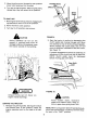
2. Loosen the inside nut until the cam lever can be pushed forward so that there is a 1/8" to 316" space between the cam fever and stop bolt. See figure 14. 3. Tighten the outside nut against the inside nut, using two 12" wrenches. See figure 14. 4. 1f there is no more adjustment left at the two nuts, tighten the hex nut on the end of the brake rod, under the spring. See figure 15. Remove the hairpin cotter and clevis pin from the other end of the brake rod to disconnect it, and tighten the nut.
A CAUTION Be sure all parts are tightened securely. LIFT CONTROL LEVER The fight control lever is used to lift or lower equipment used with the tractor. The equipment can be set in five positions by depressing the button on the lever and releasing it when the desired position is reached. See figure 18. FIGURE 18. MAINTENANCE ENGINE OIL The engine crankcases is filled with ship-away oil. This oil may be used for the first 5 hours of engine operation at temperatures between + 90 degrees F. and 0 degrees F.
Spacers Position Tangs As Shown Screws FIGURE 18.—8 H.P. Units AIR CLEANER (11 H.P. Units} 1. Remove air cleaner stud, screw and cover. See figure 20. Replace cover gasket if damaged. 2. Remove plate screw, washer and plate, 3. Remove cartridge and clean air cleaner body carefully to prevent dirt from entering carburetor. Brush dirt farm body through holes into duct. 4. Glean cartridge by tapping gently on fiat surface. a.
TRANS AXLE The trans axle is lubricated and sealed at the factory and does not require checking. If disassembled for any reason, (lubricate with 24 oz. of E.P, Lithium grease. DRIVE BELT REPLACEMENT If drive belt replacement is required, contact your authorized dealer. BATTERY INFORMATION A. Battery acid must be handled with great care as contact with it can burn and blister the skin. It is also advisable to wear protective clothing {goggles, rubber gloves and apron) when working with it.” B.
6. Battery electrolyte substitutes 7. Freezing of electrolyte NOTE: These failures do not constitute warranty. BATTERY REMOVAL OR INSTALLATION AT When removing the battery, follow this order of disassembly to prevent your wrench from shorting against the frame. 1. Remove the Negative cable. 2. Remove the Positive cable. To install a battery: 1. Attach the Positive cable. 2. Attach the Negative cable. BOOSTER BATTERIES AND CHARGING THE BATTERY A CAUTION Batteries can explode during boosting or charging.
OFF-S SEASON STORAGE 4. Remove the battery from the tractor recharge it, and adjust the electrolyte label. Store the If the machine is to be inoperative for a period battery in a dry and dark place. Never set longer than 30 days, the following procedures are directly on concrete. recommended: 5. Clean the engine and the entire tractor 1. Remove dirty engine oil, fill with new oil ang thoroughly. run the engine for about 5 minutes to let the 6. Lubricate ail lubrication points.
NOTE Check the tires for proper inflation before making a level and height adjustment. To level the mower, put the tractor on a level surface. A hard surface such as a garage floor or sidewalk is preferable. Side to Side Leveling The 36 and 44 inch mowers are equipped with two adjustable lift links. This feature allows the mower to be leveled. See figure 23. (Right Hand Side Shown) / FIGURE 23. To check the side to side leveling of the deck, place the union a hard, level surface.
STOPPING THE MOWER Move the power take-off switch to “Off” and reduce the engine speed. NOTE When installing a new belt always check the condition of the pulleys and if they are not in satisfactory condition, replace them with new pulleys available at your authorized dealer. NOTE Be sure narrow dimension of belt is in bottom of all pulley grooves. Stop the tractor, disengage the power take-off, place all controls in neutral, engage the brake lock and stop the engine before performing any maintenance.
Woad Black in Position FIGURE 27. After replacing blades, grease the threaded end of the shalt to prevent rust build-up. When replacing the blades, be sure they are assembled so the cutting edges are in the direction of rotation with the wind wings pointed upward. Tighten the nuts 50 to 60 Ibf. N-m}. NOTE 1 the spindle pulley nuts are removed for any reason, they should be re tightened to 80 to 110 Ibf. fi. (122 to 149 N-m) torque when replaced.
FIGURE 32. Sp indie Mower {See figures 33, 34 and 35.) To replace spindle drive belt, remove belt covers. Release spring tension. Remove the old belt, Install the new belt around pulleys as shown. Be certain belt is in the lower groove of the center pulley. Reinstall belt covers, FIGURE 33. FIGURE 34, 21 FIGURE 35. MOWING To avoid possible injury, do not slow anyone in the area opposite the discharge chute while mowing.
2. Operate the tractor at full throttle and lower forward speeds. 3. Keep the blades sharp and replace blades when worn. Refer to section on blade care on page 20. 4. Follow the mowing procedure shown in figure Hairpin Cotters o and Flat Wash Cut Grass ' ers e y Front Hairpin Cotter and Flat Washer FIGURE 37. 44-inch deck--assemble the front hanger assembly to the tractor as shown in figure Front Hanger Assembly FIGURE 386.
Hairpin Cotter . and Flat Washer Electric PTO Hairpin Cotter and Flat Washer \ FIGURE Side of 36-inch Deck FIGURE 42. Pull idler pulley on tractor toward the outside of the unit and place belt behind idler pulley. See Hairpin Cotter figure 43. and Flat Washer Hairpin Cotter and Flat Washer S FIGURE Side of 44.inch Deck Install spindle belt by slipping belt over electric . PTO pulley. See figure 42, FIGURE 43.
TROUBLE SHOOTING Possible Cause Possible Remedy LACK OF POWER Choke partially closed. Restricted air filter element .. Carburetor improperly adjusted . . Faulty ignition cooiiviiiaians . Open choke. Clean or replace element. Adjust carburetor. Check spark plug.” HARD TO START OR WILL NOT START No gasoline in fuel tank or carburetor Enginewillnoterank. . ...l Choked improperly, flooded engine Defective ignition or loose wiring . No spark ..
SPECIFICATIONS 805 (192) 1105 (292) 1605 (392) CAPACITIES (Approximate) Cadet Hadst Cadet Fuel Tank 3 Gallon Crankcase . .. 3 Pints Trans axle 2% Pints ENGINE Preregistration Preregistration Preregistration Make and Model 131707 253707 402707 Number of Cylinders . One One Two Bore .. inch Stroke . Displacement . 19.44 cu. in. 24.36 cu. in, 40.0 cu. in.
LUBRICATION TABLE Check | Change Anticipated Air Temperature Point of Lubrication at at Capacity Hours Hours Above +40°F. 100°F. Below 20°F. Engine crankcase Check Every Engine Oil Engine Oil Engine Oif before 30 3 Pints SADES SAE10W30 or SALESWOMAN each SAE10WA40 SALESWOMAN As Two strokes of the lubricator using 25TH EP Steering gear 25 needed grease of equivalent No. 2 multi-purpose housing lithium grease. Use 25TH EP grease or equivalent No.
STANDARD TORQUE DATA FOR INCH NUTS AND BOLTS — FOOT POUNDS As commended torque for ail Standard Unplaced Nuts and Bolts, provided: Surface finish is aide coated, oil quenched or bright All thread surfaces are clean and lubricated with SEA-30 engine oil or equivalent (Ses NOTE.) Joints are rigid, that is, no gaskets or compressible materials are used. When reusing nuts or bolts uss minimum torque values. NOTE: Multiply the standard torque by: 65 when finished jam nuts are used. -70 when Malamute.