
User Manual

MCN Remote Comparator Display Appendix A
CTI Products, Inc. Changing Status Message Text
68-10856-210
71
9.4 Input Value Format
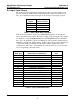
The status messages displayed for each display position are represented by four
bits in a status byte, with each bit being an input status signal. From these four
bits, up to 16 different status messages can be shown for any display position.
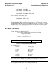
Input Status
Signal
Status Byte
Binary Weight
VOTE 01 hex
RECEIVE 04 hex
DISABLE 10 hex
FAIL 40 hex
Table 2 - Status Byte Binary Weights
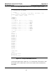
Table 2 shows the binary weight of each MCNRCD input line, along with the
name of the input status signal. The binary weights of the four input status signals
are summed to create the
input value
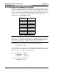
field of the MCNRCD.CFG text definition
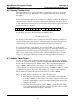
line. For your application, all valid combinations of these binary weights must be
defined by separate text definition lines. Table 3 shows the possible combinations
of the binary weights (in the Input Value Field column) and the status name
combination for the value. A column has also been provided for you to enter the
text corresponding to the input value.
Input Value
Field (hex) Status Signal Combinations
Custom
Text
00 -
01 VOTE
04 RECEIVE
05 RECEIVE + VOTE
10 DISABLE
11 DISABLE + VOTE
14 DISABLE + RECEIVE
15 DISABLE + RECEIVE + VOTE
40 FAIL
41 FAIL + VOTE
44 FAIL + RECEIVE
45 FAIL + RECEIVE + VOTE
50 FAIL + DISABLE
51 FAIL + DISABLE + VOTE
54 FAIL + DISABLE + RECEIVE
55 FAIL + DISABLE + RECEIVE + VOTE
Table 3 - Input Value Definitions