
User Manual


IOB Hardware Reference Theory of Operation
CTI Products, Inc.
68-11168-105
10
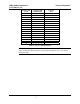
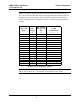
operation is shown in Table 8. The Select A invert option is selected with
OPTION switch position 3 (see section 4).
Select
A B C D E F G H
selected
output
0 0 0 0 0 0 0 0 Select A
1 1 0 0 0 0 0 0 Select B
1 0 1 0 0 0 0 0 Select C
1 0 0 1 0 0 0 0 Select D
1 0 0 0 1 0 0 0 Select E
1 0 0 0 0 1 0 0 Select F
1 0 0 0 0 0 1 0 Select G
1 0 0 0 0 0 0 1 Select H
Table 8 - Inverted Select A Operation
Note: In this table, any output shown as a 0 is a high output and any output shown
as a 1 is low output.
This can be used to drive fail-safe relays as described in Mode 2.
3.6 Custom Status Text Sub-categories
It is possible to connect different types of I/O devices (like main/standby relays
and lighting control) to a single IOB module. This is done by creating sub-
categories within a single category in the MCNRCD.CFG file. To create a sub-
category, you need to reserve one or more of the input signals in each I/O group of
the IOB module for the sub-category selector. These reserved bits are then either
left floating or strapped to ground to define the possible sub-categories. The
appendix titled
Changing Status Message Text
in the Monitoring and Control
Network Remote Comparator Display Software Manual (reference 2) has
additional information about sub-categories.
When you reserve an input signal for a sub-category selector, you are also
reserving the I/O bit associated with that input signal. The reserved I/O bits are
then used to define the sub-categories in the MCNRCD.CFG file. The following
sections show how the multiple sub-categories can be created by reserved 1, 2 or 3
I/O bits for the sub-category selector.
Section 7.4 has a system example that defines two sub-categories.