MCN Monitoring and Control Network Comparator Display System Input/Output Control Module IOB Hardware Reference Manual S2-60630-105 NOTE: This module must be configured before being installed in your system. Refer to section 4 for information about the module configuration.
FCC Statement This equipment has been tested and found to comply with the limits for a Class A digital device, pursuant to Part 15 of the FCC Rules. These limits are designed to provide reasonable protection against harmful interference when the equipment is operated in a commercial environment. This equipment generates, uses, and can radiate radio frequency energy and, if not installed and used in accordance with the instruction manual, may cause harmful interference to radio communications.
IOB Hardware Reference CTI Products, Inc. Standard Limited Hardware Warranty LIMITED WARRANTY. Equipment manufactured by CTI Products, Inc. is warranted to be free from defects in material and workmanship for a period of ONE (1) YEAR from date of shipment to original purchaser. Under this warranty, our obligation is limited to repairing or replacing any equipment proved to be defective by our inspection within one year of sale to the original purchaser.
IOB Hardware Reference CTI Products, Inc. CTI Products, Inc. 1211 W. Sharon Rd. Cincinnati, OH 45240 If you have questions about the MCN system, call us at: (513) 595-5900.
IOB Hardware Reference CTI Products, Inc. 1. INTRODUCTION......................................................................................................... 1 1.1 REFERENCE DOCUMENTS ............................................................................................... 1 2. SPECIFICATIONS....................................................................................................... 2 3. THEORY OF OPERATION................................................................................
IOB Hardware Reference CTI Products, Inc. 1. Introduction Introduction The Input/Output Control (IOB) is a member of the Monitoring and Control Network (MCN™) family of auxiliary modules. Hardware specifications, system examples, and configuration information are provided in this manual. The IOB module connects I/O devices (such as relays) to the MCN network. The IOB is used with a User Interface Module (such as a HIB) to create an I/O control system. PRODUCTS, INC.
IOB Hardware Reference CTI Products, Inc. 2.
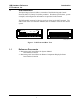
IOB Hardware Reference CTI Products, Inc. Specifications Figure 2 shows the equivalent circuits of the IOB I/O pins. The pull-up voltage Vp by jumper E1B, located on the rear of the module. • Vp = 13.8 Vdc with jumper E1B out • Vp = 5.0 Vdc with jumper E1B in Vp +5V 22K HCMOS IC INPUT 150K ESD PROTECTION 0.1uF 30V TRANSORB INPUT +5V 180K Vp 22K ESD PROTECTION 30V TRANSORB 0.1uF OUTPUT Vp 22K ESD PROTECTION +5V HCMOS IC INPUT 30V TRANSORB 150K 0.
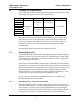
IOB Hardware Reference CTI Products, Inc. 3. Theory of Operation Theory of Operation This section describes the operation of the IOB module in an I/O control system. This module can operate in one of four different modes: I/O Group 1 2 3 4 5 6 7 8 Mode 1 Mode 2 Mode 3 1 of 4 Select #1 1 of 4 Select Independent I/O Mode 4 1 of 8 Select 1 of 4 Select #2 Independent I/O The operating mode is set using the OPTION switches on the module’s front panel.
IOB Hardware Reference CTI Products, Inc. Theory of Operation An IOB has 8 I/O groups (similar to the 8 receivers per CIB module). Since each I/O group is represented by four I/O points, a maximum of 32 I/O points can be displayed per IOB. When configuring your MCNRCD screens for IOB modules, know that each I/O group is related to an Rx # in the MCNRCD and MCNCFG software. I/O group 1 is the same as Rx # 1 and so on through I/O group 8 is the same as Rx # 8. The basic IOB module is setup as 8 I/O groups.
IOB Hardware Reference CTI Products, Inc. Theory of Operation Input Value Field 00 01 04 05 10 11 14 15 40 41 44 45 50 51 54 55 Active I/O Bit Combinations 1 2 2+1 3 3+1 3+2 3+2+1 4 4+1 4+2 4+2+1 4+3 4+3+1 4+3+2 4+3+2+1 Custom Text Table 3 - Input Value Definitions Note: The IOB’s inputs and outputs are active low. Therefore, for a I/O bit to be active, it must be pulled to ground. Also, when an output is active, it is driven low by the IOB.
IOB Hardware Reference CTI Products, Inc. 3.1.2 Theory of Operation Output Control As stated earlier in this section, the output points of the IOB module can be controlled by both the mouse and keyboard. Table 4 shows which I/O bits are controlled by the specific mouse or keyboard buttons. To control the I/O bit, simply move the cursor over the I/O group that represents the I/O bit and click the proper mouse button or press the proper keyboard button. The IOB output point will change state.
IOB Hardware Reference CTI Products, Inc. 3.2 Theory of Operation Mode 1 - General Purpose I/O - 16 Outputs In general purpose I/O mode, the IOB module provides 16 input/output lines and 16 input only lines. Table 16 shows the pinout for this mode as well as the I/O group and I/O bit number associated with each connector pin. 3.3 Mode 2 - Two Sets of 1 of 4 Select Output In this mode, the IOB provides two sets of 1 of 4 Select output lines and 24 input only lines.
IOB Hardware Reference CTI Products, Inc. Theory of Operation This option is typically used when you need 1 of 4 relays that will operate in a fail-safe mode when the power fails. For instance, you can drive 4 DPDT relays to provide a 1 of 4 manual transmitter selection circuit. Transmitters 2 through 4 would be connected to the normally open relay contacts, while transmitter 1 would be connected to the normally closed contacts. If the power fails, the system will revert to transmitter 1. 3.
IOB Hardware Reference CTI Products, Inc. Theory of Operation operation is shown in Table 8. The Select A invert option is selected with OPTION switch position 3 (see section 4).
IOB Hardware Reference CTI Products, Inc. Theory of Operation Creating Two Sub-categories To create two sub-categories, one I/O bit must be reserved for the sub-category selector. In Table 9, I/O bit 4 has been reserved for the sub-category selector. You can see from the table that there are eight possible status messages that can be defined for each sub-category. Because I/O bit 4 has been reserved as the selector, all IOB pins that correspond to I/O bit 4 cannot be used by application circuitry.
IOB Hardware Reference CTI Products, Inc. Theory of Operation Creating Four Sub-categories To create four sub-categories (for four different I/O types), two I/O bits must be reserved for the sub-category selector. In Table 10, I/O bits 3 and 4 have been reserved for the sub-category selector. You can see from the table that there are four possible status messages that can be defined for each sub-category.
IOB Hardware Reference CTI Products, Inc. Theory of Operation Creating Eight Sub-categories To create eight sub-categories, three I/O bits must be reserved for the sub-category selector. In Table 10, I/O bits 2, 3 and 4 have been reserved for the sub-category selector. You can see from the table that there are two possible status messages that can be defined for each sub-category.
IOB Hardware Reference CTI Products, Inc. 4. Option Switches and Jumpers Option Switches and Jumpers Three sets of option switches are provided for module configuration. The module must be power cycled or reset after these switches are set so that the options will take effect. Table 12 describes the option switches and shows the factory defaults.
IOB Hardware Reference CTI Products, Inc. Option Switches and Jumpers The Select A Invert switch (OPTION switch position 3) is only used when operating modes 2, 3 or 4 are selected (in mode 1, this switch is not used). The switch is defined as: Option Switch 3 DOWN UP Function Inverted Select A Outputs (active low) Normal Select A Outputs (active high) This switch only affects the Select A output lines. All other Select output lines are active low.
IOB Hardware Reference CTI Products, Inc. Option Switches and Jumpers E1 A E1 B CA-80024-100 Figure 3 - Jumper Options Jumper E1A is located across the top 2 terminals of the 6 pin terminal block. This jumper is reserved and should not be installed. Jumper E1B is located across the left side middle and bottom terminals of the 6 pin terminal block. Set this jumper to match the needs of your I/O system. The remaining 2 terminals of the block are unused.
IOB Hardware Reference CTI Products, Inc. 5. Connectors Connectors The NETWORK IN/OUT ports on the front of the IOB are used to connect the IOB with other MCN modules. These ports carry both the network data signals as well as DC power for power distribution with other modules. . Table 15 gives the pinout for these connectors. Figure 4 shows the location of pin 1 for each port. PRODUCTS, INC.
IOB Hardware Reference CTI Products, Inc. Connectors Changing Status Message Text in the Monitoring and Control Network Remote Comparator Display Software Manual (reference 2) for more information about custom text messages.
IOB Hardware Reference CTI Products, Inc.
IOB Hardware Reference CTI Products, Inc. 6. Mounting Mounting Refer to the Monitoring and Control Network System Manual (reference 1), section Mounting Options, for details about mounting the IOB module. CAUTION Make sure that any mounting screws used to secure unit to a bracket do not protrude into the unit’s enclosure more than 1/8 inches from the bottom surface of the unit. Using a larger screw that touches the pc board inside the unit may damage the unit when it is powered.
IOB Hardware Reference CTI Products, Inc. 7. System Examples System Examples This section contains various examples that describe the different operating modes of the IOB module. 7.1 General Purpose I/O Example Figure 5 shows a general purpose I/O system that is monitored from a local PC.
IOB Hardware Reference CTI Products, Inc. Input Value Field 00 01 04 05 10 11 14 15 40 41 44 45 50 51 54 55 System Examples Active I/O Bit Combinations 1 2 2+1 3 3+1 3+2 3+2+1 4 4+1 4+2 4+2+1 4+3 4+3+1 4+3+2 4+3+2+1 Custom Text Run Active Run/Act Step Run/Step Step/Act Run/Act Fail Fail/Run Fail Fail/Run Fail/Step Fail Fail/Step Fail Table 19 - Custom Text for General I/O System From this table we can now create our custom status text category in the MCNRCD.CFG file.
IOB Hardware Reference CTI Products, Inc. 7.2 System Examples One of Four Select I/O Example Figure 6 shows an I/O system that uses the IOB in 1 of 4 Select mode. The four Select outputs are connected to relay controls and the four PTT inputs are connected to input pins of the IOB.
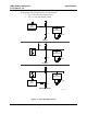
IOB Hardware Reference CTI Products, Inc. System Examples IOB CIRCUIT USER APPLICATION CIRCUIT I/O BIT I/O GROUP 1-4 1 TX SELECT (OUTPUT) 2 PTT (INPUT) 3 NO CONNECT 4 NO CONNECT CA-80276-100 Figure 7 - 1 of 4 Select I/O Bit Configuration (Tx Select and PTT) From the figure, you can see that relay control lines are connected to the Select 1A through D outputs of the IOB. These outputs correspond to I/O bit 1 of I/O groups 1 through 4 .
IOB Hardware Reference CTI Products, Inc. 7.3 System Examples Inverted Select A Example For this example, assume we have the same system as in section 7.2, but we need to changed the system so that the TX 1 Select relay is normally closed (so that if the power fails, the TX 1 Select relay will be engaged). Figure 8 shows this modified system drawing.
IOB Hardware Reference CTI Products, Inc. 7.4 System Examples Sub-category Example Figure 9 shows a system that uses a single IOB module to monitor two different types of input devices. One set of input devices are alarm input and the other set of input devices are control inputs. Because the IOB is monitoring two different input device types, we need to divide the IOB’s status text category in the MCNRCD.
IOB Hardware Reference CTI Products, Inc. System Examples Since there are two sub-categories defined in this system, we need to reserve one of the I/O bits for the sub-category selector. Figure 9 shows that I/O bit 4 (FAIL) is reserved for the sub-category selector. Because I/O bit 4 is reserved, we cannot use any IOB I/O pins that correspond to I/O bit 4 (see Table 16) as general purpose I/O pins. Table 21 shows how the sub-category selector bit operates.
IOB Hardware Reference CTI Products, Inc. 8. Troubleshooting Troubleshooting This table is a list of troubleshooting tips specific to the IOB module. For additional troubleshooting tips, refer to the troubleshooting section found in the Monitoring and Control Network System Manual (reference 1). Due to the high percentage of surface-mount components the IOB is treated as a field replaceable unit.