
Instruction Manual
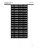
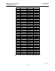
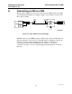

IIB Hardware Reference Connecting an IIB to a CEB
CTI Products, Inc.
68-10844-115
20
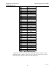
IIB
J1
Function Connect to
16 I/O Bd (A or B) - Pin
21 Vote 1 A - 26
19 Rx 1 A - 27
20 Dis 1 A - 28
23 Fail 1 A - 29
46 Vote 2 A - 30
44 Rx 2 A - 31
45 Dis 2 A - 32
48 Fail 2 A - 33
15 Vote 3 A - 34
12 Rx 3 A - 35
14 Dis 3 A - 36
17 Fail 3 A - 37
40 Vote 4 A - 38
37 Rx 4 A - 39
39 Dis 4 A - 40
42 Fail 4 A - 41
9 Vote 5 B - 26
6 Rx 5 B - 27
8 Dis 5 B - 28
11 Fail 5 B - 29
34 Vote 6 B - 30
31 Rx 6 B - 31
33 Dis 6 B - 32
36 Fail 6 B - 33
3 Vote 7 B - 34
18 Rx 7 B - 35
2 Dis 7 B - 36
5 Fail 7 B - 37
28 Vote 8 B - 38 *
26 Rx 8 B - 39 *
27 Dis 8 B - 40 *
30 Fail 8 / Link Fail B - 41 *
4 Link Fail Enable tie to IIB J1 pin 1 to enable
the Link Fail feature
1 Ground A & B 1 through 16
Table 7 - IIB to CEB Connections
* Signals for receiver 8 are active only if the Link Fail Enable (J1 pin 4) is open
(Link Fail feature is disabled). If J1 pin 4 is grounded, J1 pin 30 becomes a Link
Fail output and J1 pins 26, 27 and 28 become unused pins.