MCN Monitoring and Control Network Comparator Display System Input/Output Interface Module IIB Hardware Reference Manual S2-60400-115 68-10844-115
FCC Statement This equipment has been tested and found to comply with the limits for a Class A digital device, pursuant to Part 15 of the FCC Rules. These limits are designed to provide reasonable protection against harmful interference when the equipment is operated in a commercial environment. This equipment generates, uses, and can radiate radio frequency energy and, if not installed and used in accordance with the instruction manual, may cause harmful interference to radio communications.
IIB Hardware Reference CTI Products, Inc. Standard Limited Hardware Warranty LIMITED WARRANTY. Equipment manufactured by CTI Products, Inc. is warranted to be free from defects in material and workmanship for a period of ONE (1) YEAR from date of shipment to original purchaser. Under this warranty, our obligation is limited to repairing or replacing any equipment proved to be defective by our inspection within one year of sale to the original purchaser.
IIB Hardware Reference CTI Products, Inc. CTI Products, Inc. 1211 W. Sharon Rd. Cincinnati, OH 45240 If you have questions about the MCN comparator display system, call us at: (513) 595-5900.
IIB Hardware Reference CTI Products, Inc. 1. INTRODUCTION..................................................................................................... 1 1.1 REFERENCE DOCUMENTS ........................................................................................... 1 2. SPECIFICATIONS ................................................................................................... 2 3. THEORY OF OPERATION .................................................................................... 4 3.
IIB Hardware Reference CTI Products, Inc. 1. Introduction Introduction The Input/Output Interface Module (IIB) is a member of the Monitoring and Control Network (MCN™ ) family of User Interface Modules. Hardware specifications, special installation, and configuration information are described in this manual. The IIB module connects a parallel operator display device (such as a console) to the MCN network.
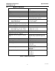
IIB Hardware Reference CTI Products, Inc. 2. Specifications Specifications Size 5.5” x 4.2” x 1.5” (140 x 107 x 38 mm) 16 oz (455 gm) 0 - 50 ºC 10 - 95% non-condensing 10 - 32 Vdc / 2 Watts max. 8 (Link Fail feature disabled) 7 (Link Fail feature enabled) Weight Temperature Humidity Module Power Number of Receivers Supported Open Circuit Voltage (all I/O pins) jumper E1B removed jumper E1B installed Inputs per Receiver active low, pull-up to +5 or +13.
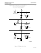
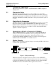
IIB Hardware Reference CTI Products, Inc. Specifications Figure 2 shows the equivalent circuits of the IIB I/O pins. The pull-up voltage Vp by jumper E1B, located on the rear of the module. • Vp = 13.8 Vdc with jumper E1B out • Vp = 5.0 Vdc with jumper E1B in Vp +5V 22K HCMOS IC INPUT 150K ESD PROTECTION 0.1uF 30V TRANSORB INPUT +5V Vp 180K 22K ESD PROTECTION 30V TRANSORB 0.1uF OUTPUT Vp 22K ESD PROTECTION +5V HCMOS IC INPUT 30V TRANSORB 150K 0.
IIB Hardware Reference CTI Products, Inc. 3. Theory of Operation Theory of Operation This section describes the operation of the IIB module in an MCN comparator display system. 3.1 Comparator Status The Comparator I/O Module (such as an AIB or CIB) accepts the VOTE, RECEIVE, DISABLE, and FAIL receiver status indicators from the comparator. It sends status messages to the IIB module.
IIB Hardware Reference CTI Products, Inc. Theory of Operation If the comparator detects that a receiver has failed, it sends a FAIL command to the Comparator I/O Module. Again, the Comparator I/O Module sends this FAIL command to the IIB so that the user can see that the receiver has failed. From the console, the user can generate FORCE VOTE or DISABLE commands for each receiver in the system.
IIB Hardware Reference CTI Products, Inc. 3.6 Theory of Operation Parallel I/O Signals The IIB provides two input/output lines per receiver (VOTE and DISABLE) that allow both monitoring and control of the signal. Two output only lines per receiver (FAIL and RECEIVE) are also provided. None of these I/O lines are latched in the IIB. In the console, the VOTE switch or button should be momentary, and the DISABLE switch or button should be latched.
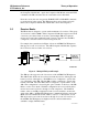
IIB Hardware Reference CTI Products, Inc. 3.8 Theory of Operation Example Connections to a Console Figure 5 shows how an IIB may be connected to a console. Notice that the VOTE and DISABLE lines between the IIB and the console are bi-directional.
IIB Hardware Reference CTI Products, Inc. 4. Option Switches Option Switches Three sets of option switches are provided for module configuration. The module must be power cycled or reset after these switches are set so that the options will take effect. Table 2 describes the option switches and shows the factory defaults.
IIB Hardware Reference CTI Products, Inc. Option Switches When the IIB is used with a Comparator I/O Module that supports only 8 receivers, such as a CIB, bank 0 will always be used. Figure 6 shows the configuration of the two jumper options available on the rear of the IIB. These jumpers should be installed at system installation time with power removed from the IIB. E1 A E1 B CA-80024-100 Figure 6 - Jumper Options Jumper E1A is located across the top 2 terminals of the 6 pin terminal block.
IIB Hardware Reference CTI Products, Inc. 5. Connectors Connectors The NETWORK IN/OUT ports on the front of the IIB are used to connect the IIB with other MCN modules. These ports carry both the network data signals as well as DC power for power distribution with other modules. . Table 4 gives the pinout for these connectors. Figure 8 shows the location of pin 1 for each port. PRODUCTS, INC.
IIB Hardware Reference CTI Products, Inc. Signal VOTE RX DIS FAIL Connectors Direction Description Input/Output Output activated when comparator votes that receiver. Ground input to force vote a receiver. Output Activated when comparator detects a valid signal on the receiver. Input/Output Output activated when receiver is disabled by comparator. Ground input to disable the receiver. Output Activated when receiver failure is detected by the comparator.
IIB Hardware Reference CTI Products, Inc.
IIB Hardware Reference CTI Products, Inc.
IIB Hardware Reference CTI Products, Inc. Special Installation Instructions 6. Special Installation Instructions 6.1 Unit Address Setting An IIB must be programmed with two unit addresses: 1. the address of the Comparator I/O Module it will operate with 2. the IIB’s own address You only need to perform this programming once, at installation time.
IIB Hardware Reference CTI Products, Inc. Special Installation Instructions the unit address programming steps.
IIB Hardware Reference CTI Products, Inc. Special Installation Instructions For example, Figure 10 shows a system with a single IIB and Comparator I/O Module. The following steps show how the system might be setup, using the following address assignments: • IIB address is Group 80, Module 0 • Comparator I/O Module is Group 00, Module 0 Step 1 2 3 4 5 6 7 7 8 9 10 11 12 13 Action Connect the network cable between the IIB NETWORK OUT port and the Comparator I/O Module’s NETWORK IN port.
IIB Hardware Reference CTI Products, Inc. 7. Special Features 7.1 Link Failure Reporting Special Features The IIB has a selectable option to show communication link failures between the IIB and its Comparator I/O Module (network link failures) or between the Comparator I/O Module and the comparator (comparator link failures). With this option enabled, the IIB will always report network link failures.
IIB Hardware Reference CTI Products, Inc. 8. Mounting Mounting Refer the reference 1, section Mounting Options, for details about mounting the IIB module. CAUTION Make sure that any mounting screws used to secure unit to a bracket do not protrude into the unit’s enclosure more than 1/8 inches from the bottom surface of the unit. Using a larger screw that touches the pc board inside the unit may damage the unit when it is powered. Doing so will void the unit’s warranty.
IIB Hardware Reference CTI Products, Inc. 9. Connecting an IIB to a CEB Connecting an IIB to a CEB The following example shows how you would connect an IIB to Motorola’s CEB (Central Electronics Bank) in a comparator display system. Figure 11 shows what this system looks like.
IIB Hardware Reference CTI Products, Inc.
IIB Hardware Reference CTI Products, Inc. 10. Troubleshooting Troubleshooting This table is a list of troubleshooting tips specific to the IIB module. For additional troubleshooting tips, refer to the troubleshooting section found in the Monitoring and Control Network System Manual, reference 1. Due to the high percentage of surface-mount components the IIB is treated as a field replaceable unit.