
User guide

68-11089-115
9
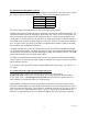
"CMD" button
-- currently not used.
"OPTION A" switches --
1-4 Reserved. All switches must be UP.
5 Normal Systems: leave Up
Custom Engineered Systems, set as indicated in Custom Documentation
6-8 Reserved. All switches must be UP.
EXB Serial Rear Panel
CA-80286-105
1
2
34
ON
8
9
7
A
B
C
D
E
F
0
1
2
3
4
5
6
8
9
7
A
B
C
D
E
F
0
1
2
3
4
5
6
8
9
7
A
B
C
D
E
F
0
1
2
3
4
5
6
OPTION B
PORT 1 PORT 2
BAUD 1 BAUD 2
1234
6789
5
1234
6789
5
8
9
7
A
B
C
D
E
F
0
1
2
3
4
5
6
MODE 1 MODE 2
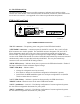
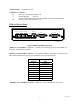
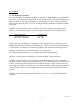
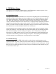
Figure 4 EXB-Serial Module Rear Panel
“PORT 1” and “PORT 2”
connectors -- Provide for connecting up to two external RS-232
devices to the EXB-Serial module.
“BAUD 1” and “BAUD 2” switches
-- Correspond to PORT 1 and PORT 2 connectors and
allow either disabling the port for use or enabling it at a specific baud rate.
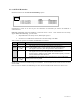
BAUD Switch
Position
Selected Baud
Rate
0 port disabled
1 1200
2 2400
3 4800
4 9600
5 19.2 K
6 38.4 K
7 57.6 K
8 115.2 K
“MODE 1” and “MODE 2” switches
-- Reserved. These switches must be set to 0.