Monitoring and Control Network Extender Module (EXB) User Documentation S2-60596-115 CTI Products, Inc. 1211 West Sharon Road Cincinnati, Ohio 45240 (513) 595-5900 (513) 595-5983 Fax Information contained in this document is subject to change without notice and does not represent a commitment on the part of CTI Products, Inc.
Standard Limited Hardware Warranty LIMITED WARRANTY. Equipment manufactured by CTI Products, Inc. is warranted to be free from defects in material and workmanship for a period of ONE (1) YEAR from date of shipment to original purchaser. Under this warranty, our obligation is limited to repairing or replacing any equipment proved to be defective by our inspection within one year of sale to the original purchaser.
Table of Contents 1. INTRODUCTION................................................................................................................................. 1 1.1 REFERENCE DOCUMENTS ................................................................................................................ 2 1.2 EXB COMMUNICATION CHANNEL INTERFACES ............................................................................... 3 1.2.1 EXB-TELCO Communication Channel Interface ...................................
Manual Revisions Rev. Date 110 115 10/12/2002 Description Original Release Added extended baud rate table, Option B switch description (RS232 Handshake Control), User supplied DC Power Supply information, and Custom Engineered System operation.
1. Introduction The Extender Module (EXB) is used in pairs to connect multiple MCN modules in real-time, spanning distances from building-wide to worldwide. Two types of EXB modules are available, supporting different communication channels that connect the remote networks. The EXBTELCO module supports any analog or digitized analog channel that is capable of carrying V.32 terbo standard modem signaling, including 2-wire or 4-wire leased lines or microwave channels.
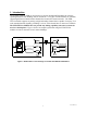
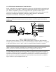
The second type of EXB module is the EXB-Serial Module. This module interfaces with a virtual RS-232 communications channel (such as a high speed fractional T1 circuit). Figure 2 shows an example system using the EXB-Serial modules to connect networks in two remote buildings.
1.2 EXB Communication Channel Interfaces This section describes the communication channel interface of the EXB-TELCO module and the EXB-Serial module. This interface provides the network connection between the remote MCN networks. 1.2.1 EXB-TELCO Communication Channel Interface The internal modem in the EXB-TELCO module uses proven V.32 terbo modulation, transferring data at 19,200 bits per second.
1.2.2 EXB-Serial Communication Channel Interface PORT 1 and PORT 2 are standard asynchronous serial ports with individually configurable baud rates from 1200 to 115.200 BPS. An RS-232 communication channel can be connected to each port. PORT 1 and PORT 2 pinouts are configured for DTE operation and allow direct connection to an RS-232 communication channel via a standard 9 pin to 25 pin cable, provided the RS-232 communication channel is configured for DCE operation.
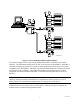
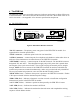
T P/S COMPARATORS OUT IN CIB 1 CIB 2 CIB 3 OUT LOCAL PC T P/S IN IN HIB COM 2 COM 1 IN OUT T EXB SERIAL OUT IN OUT T1 MUX EXB T1 MUX PORT 1 SERIAL OUT IN PORT 1 T1 MUX T P/S PORT 2 T P/S COMPARATORS OUT IN CIB 1 CIB 2 CIB 3 OUT IN OUT IN T1 MUX EXB SERIAL PORT 1 OUT IN T P/S CA-80304-100 Figure 4 - Two Port EXB-Serial Module System Example The system in Figure 4 shows how a single EXB-Serial module is connected to two remote networks.
2. The EXB Unit The EXB unit contains user accessible connectors, indicators and controls to allow efficient use of the EXB module. This section describes the function of each item. More detail of the use of each is in section 3. See Appendix A for connector specifications and pinouts. 2.
"RESET" pushbutton -- Hardware reset for the entire EXB-TELCO module. Non-volatile information is retained. "CMD" pushbutton -- currently not used. "CSVC" pushbutton -- reserved. Used during configuration of custom engineered systems. See the custom configuration documents for your system. "RSVC" pushbutton -- reserved -- Used during configuration of custom engineered systems. See the custom configuration documents for your system.
2.2 The EXB-Serial Unit The EXB-Serial unit contains user accessible connectors, indicators and controls to allow efficient use of the module. This section describes the function of each item. More detail of the use of each is in section 3. See Appendix A for connector specifications and pinouts.
"CMD" button -- currently not used. "OPTION A" switches -1-4 Reserved. All switches must be UP. 5 Normal Systems: leave Up Custom Engineered Systems, set as indicated in Custom Documentation 6-8 Reserved. All switches must be UP.
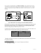
2.2.1 OPTION B Switches OPTION B switches set the Serial Port Handshaking options. ON 1 2 3 4 DOWN 1. PORT 1 CTS sense..........................Disabled 2. PORT 1 DSR sense .........................Disabled 3. PORT 2 CTS sense..........................Disabled 4. PORT 2 DSR sense .........................Disabled UP Enabled (Normal) Enabled (Normal) Enabled (Normal) Enabled (Normal) CTS/RTS flow control can be used to pace the transmission of individual bytes between the EXB and a connected device.
3. EXB Module Setup The EXB module requires minimal setup for ease of installation. This section details setup requirements for mounting, connection, and controls. 3.1 Physical Non-slip rubber feet are included on all EXB modules to allow them to conveniently rest on any horizontal surface. Four 6-32 threaded holes are also available on the bottom of the module to allow bolting of the module in any convenient orientation.
3.2.4 EXB-TELCO Handset Connection A standard telephone handset or other audio input and output device may be connected to the "AUDIO" connector to allow use of the simultaneous voice/data feature of the EXB-TELCO module. Audio directly from the telephone circuit is routed to this connector during training to permit monitoring of call establishment (as typical modems provide via an internal speaker).
3.3 Controls 3.3.1 EXB-TELCO Controls The 8 position DIP switch labeled "OPTION A" provides for EXB module static configuration. Section 2.1 of this manual lists the function of each switch position. This section details how to set the switches for each type of intended use. The OPTION A switch is read by the internal EXB circuits at module power up or after pressing the RESET pushbutton on the EXB module front panel.
3.3.2 EXB-Serial Controls The front panel "OPTION A" switches as well as the rear panel “OPTION B”, “BAUDn” and “MODEn” switches provide for EXB module static configuration. Section 2.2 of this manual lists the function of each switch position. This section details how to set the switches for each type of intended use. The switches are read by the internal EXB circuits at module power up or after pressing the RESET pushbutton on the EXB module front panel.
RS-232 Hardware Handshake Controls The EXB-Serial module uses the hardware handshake control lines to control the flow of data to and from the RS-232 communication channel. These control signals are listed below. Control Signal Direction RTS Output CTS Input DSR Input DTR Output The control signals DCD and RI are not used by the EXB-Serial module. The RTS and CTS lines control the flow of characters to and from the EXB-Serial module.
4. EXB Module Usage Once properly connected and configured for use, the EXB module is simple to operate. Runtime operation of the EXB module is completely automatic. 4.1 EXB-TELCO Usage After power up or reset, an EXB module set to Leased-Line Originate mode will immediately go off hook and emit a cyclic calling tone to the telephone circuit. An EXB module set to LeasedLine Answer mode will go off hook and wait for detection of the calling tone from the distant end.
Appendix A EXB Module Connectors DC IN Connector Connector type: 2.5 x 5.5 mm coaxial Mating Connector: Switchcraft 760 or equivalent Connector pinout: CTI Products, Inc. standard power supply wired with center pin positive, EXB module can accept either pin positive, polarity routing is provided internal.
building 1 is powering 2 module loads for each IIB plus 2 module loads for the EXB for a total of 4 module loads on the power supply. If another MCN module is added to the MCN network in either building, an additional power supply would have to be added to the system for the additional module. Powering the EXB unit from a customer-supplied DC source When powering the unit from a customer-furnished power supply, the supply must be current limited or fused at 1A.
EXB-TELCO Module LINE Connector Connector type: standard RJ11 telephone style, 6 position 4 contact. For 2 wire leased-line operation, connect pins 3 and 4 from each EXB module to each end of the bidirectional leased-line circuit. For 4 wire leased-line operation: • connect pins 3 and 4 of EXB module 1 to the circuit carrying audio from EXB1 to EXB2, terminate this circuit to pins 2 and 5 of EXB2.
EXB-Serial Module PORT 1 and PORT 2 Connectors Connector type: standard DE9 male Pinout as DTE (PC-AT pinout) In general, all signals (except RI and DCD) must be connected for proper operation.
Appendix B EXB Module Specifications DC Power Input: 10 to 30 VDC, unregulated Input Power: 5 watts maximum - this counts as two MCN module loads when using network cable power distribution. DC Drop: 1.4 VDC drop from Power input (or Network In) connector to Network Output connector. Size: 7.5” D x 5.6” W x 1.6” H Operating Temperature: 0 to 60 °C Humidity: 10-95% non-condensing Mounting: Desktop with integral non-slip feet Wallmount or 19” rack mount with optional adapters Modem: (EXB-TELCO Only) V.
Appendix C EXB Mounting Options Wall mount and EIA 19” rack mount kits are available as options for the EXB from CTI Products, Inc. The wall mount kit includes brackets to allow a single EXB module to be mounted to any flat surface. The rack mount kit includes an adapter allowing up to three EXB modules to be mounted in a single rack unit height. Wall Mount Option The wall mount option allows an EXB module to be mounted to any flat surface. The EXB module has four screw holes on the bottom.
Rack Mount Option The rack mount option allows up to three EXB modules to be mounted in a one rack unit height (1.75 inches) of a standard 19 inch rack. The modules are mounted in the rack plate by removing its’ front bezel and remounting the module into the rack plate. Figure 13 shows an exploded view of the rack mount installation. The top diagram shows the front view of the bracket with one module installed.
To attach a module to the rack adapter, and then mount the rack adapter into the rack, follow the steps below. WARNING Do not allow the PC board to slide out of the housing when the front panel is removed. If it does, DO NOT slide the PC board back into the housing from the front of the module. Doing so may damage the unit, causing the unit to malfunction when powered on. Doing so will void the unit’s warranty.
Appendix D Application Notes Using the EXB-TELCO Module with Motorola STARPLEX Microwave System This application note describes how Motorola’s STARPLEX microwave system can be used to extend the range of an MCN network. The two MCN networks are connected to the STARPLEX system using a pair of MCN Extender (EXB) Modules as shown in the diagram below.
EXB Module Phone Line Level Setting Transmit: If you are using standard STARPLEX modems and terminations, set the transmit level on the EXB module to -16 dBm (Option A switch position 7 down). The standard TX attenuator pad in the STARPLEX termination board is 10 dB. This combination provides the standard -26 dBm level on the 4-wire TX input to the modem itself.
Appendix E 1. 2. 3. 4. FCC Notices The Federal Communications Commission (FCC) has established Rules which permit this device to be directly connected to the telephone network. Standardized jacks are used for these connections. This equipment should not be used on party lines or coin lines. If this device is malfunctioning, it may also be causing harm to the telephone network; this device should be disconnected until the source of the problem can be determined and until repair has been made.