
Manual


CIB Hardware Reference Connectors
CTI Products, Inc.
68-10854-135
11
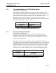
5. Connectors
The
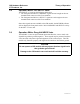
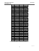
NETWORK IN/OUT
ports on the front of the CIB are used to connect the
CIB with other MCN modules. These ports carry both the network data signals as
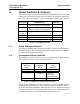
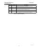
well as DC power for power distribution with other modules. Table 7 gives the
pinout for these connectors. Figure 5 shows the location of pin 1 for each port.
CA-80068-100
DC IN
IN
OUT
NETWORK
PRODUCTS, INC.
PIN 1
Figure 5 - Network IN/OUT Ports
Pin Function
1 DATA +
2 DATA -
3+ POWER
4 No Connect
5 No Connect
6- POWER
7- POWER
8+ POWER
Table 7 - Network Connector Pinout
The
DC IN
port provides the primary power connection to the module. Power is
distributed through the
NETWORK OUT
connector to provide power to the
NETWORK IN
connector of the MCN unit it is connected to. Each power
supply can power up to four units total. See reference 1 for complete details of
connections to the network and DC IN connectors.
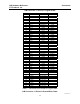
Connector J1 provides the discrete I/O for the receiver signals. Table 9 gives the
pinout for this connector. Table 8 describes the functions of the I/O signals.