
Manual


CIB Hardware Reference Option Switches
CTI Products, Inc.
68-10854-135
8
4. Option Switches & Jumpers
Three sets of option switches are provided for module configuration. The module
must be power cycled or reset after these switches are set so that the options will
take effect. Table 2 describes the option switches and shows the factory defaults.
SWITCH DESCRIPTION DEFAULT
GROUP unit address setting (00-FE)
refer to the MCN System Manual
00
MODULE unit address setting (0-F)
refer to the MCN System Manual
0
OPTION
position 1
comparator selector 1 (see Table 3) DOWN
position 2 comparator selector 2 (see Table 3) DOWN
position 3 transmitter monitoring enable DOWN
position 4 force-vote timeout DOWN
Table 2 - CIB Option Switches
4.1 Group & Module Switches
The Group and Module selector switches are used to set the node address during
module installation. Refer to the Monitor and Control Network System Manual
for details about setting these switches.
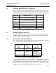
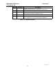
4.2 Comparator Selector Switches
The comparator selector switches set the type of comparator the CIB is operating
with. Settings for these switches are shown in Table 3.
Comparator
Selector 1
SW 1
Comparator
Selector 2
SW 2
Comparator
Type
Selected
DOWN DOWN Spectra TAC
DOWN UP Digitac
UP DOWN TAC, G.E.,
JPS SNV-12,
Doug Hall 4RV/2
UP UP other
Table 3 - Comparator Selector Switch Settings
If your specific comparator is not listed in Table 3, set both comparator selection
switches to the UP position for “other”. With this setting, the CIB will monitor
the VOTE, RECEIVE, DISABLE, and FAIL inputs from the comparator and pass
the status information to the display interface module. Also, the display interface
module can control the VOTE and DISABLE outputs of the CIB.