MCN Monitoring and Control Network Comparator Display System Comparator I/O Module CIB Hardware Reference Manual S2-60426-135 Note: Jumpers & switch settings vary depending upon the type of comparators or voters used. Be sure to verify jumper and switch settings before connecting the units to your comparators or voters. Be sure to set the rotary address switches to the proper addresses before installing the system.
FCC Statement This equipment has been tested and found to comply with the limits for a Class A digital device, pursuant to Part 15 of the FCC Rules. These limits are designed to provide reasonable protection against harmful interference when the equipment is operated in a commercial environment. This equipment generates, uses, and can radiate radio frequency energy and, if not installed and used in accordance with the instruction manual, may cause harmful interference to radio communications.
CIB Hardware Reference CTI Products, Inc. Standard Limited Hardware Warranty LIMITED WARRANTY. Equipment manufactured by CTI Products, Inc. is warranted to be free from defects in material and workmanship for a period of ONE (1) YEAR from date of shipment to original purchaser. Under this warranty, our obligation is limited to repairing or replacing any equipment proved to be defective by our inspection within one year of sale to the original purchaser.
CIB Hardware Reference CTI Products, Inc. Manual Revisions: S2-60426-100 Original Release S2-60426-105 Minor revisions S2-60426-110 Added description for Option Switch 3 (TIB Support) for CIBs version 105 and up. S2-60426-115 Added description for Option Switch 4 (Force Vote Timeout) for CIBs version 110 and up. Added instructions for JPS SNV-12 voters and Doug Hall 4RV/2 Voters. Re-formatted wiring tables.
CIB Hardware Reference CTI Products, Inc. TABLE OF CONTENTS 1. INTRODUCTION .................................................................................................................. 1 1.1 REFERENCE DOCUMENTS .................................................................................................... 1 2. SPECIFICATIONS ................................................................................................................ 2 3. THEORY OF OPERATION ..................................
CIB Hardware Reference CTI Products, Inc.
CIB Hardware Reference CTI Products, Inc. 1. Introduction Introduction The Comparator Interface Module (CIB) is a member of the Monitoring and Control Network (MCN™) family of Comparator I/O Modules. Hardware specifications, special installation, and configuration information are described in this manual. The CIB module connects a parallel I/O comparator to the MCN network.
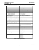
CIB Hardware Reference CTI Products, Inc. 2. Specifications Specifications Size 5.5” x 4.2” x 1.5” (140 x 107 x 38 mm) 16 oz (455 gm) 0 - 50 ºC 10 - 95% non-condensing 10 - 32 Vdc / 2 Watts max.
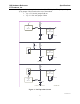
CIB Hardware Reference CTI Products, Inc. Specifications Figure 2 shows the equivalent circuits of the CIB I/O pins. The pull-up voltage Vp by jumper E1B, located on the rear of the module. • Vp = 15 Vdc with jumper E1B out • Vp = 5.0 Vdc with jumper E1B in Vp +5V 22K HCMOS IC INPUT 150K ESD PROTECTION 0.01uF 30V TRANSORB INPUT +5V Vp 180K 22K ESD PROTECTION 0.01uF 30V TRANSORB OUTPUT Vp 22K ESD PROTECTION +5V HCMOS IC INPUT 30V TRANSORB 150K 0.
CIB Hardware Reference CTI Products, Inc. 3. Theory of Operation Theory of Operation This section describes the operation of the CIB module in an MCN comparator display system. 3.1 Comparator Status The CIB can accept VOTE, RECEIVE, DISABLE, and FAIL receiver status indications from the comparator. Some comparators do not support all of these status monitoring signals. Refer to section 7 for details about wiring the CIB to a particular comparator.
CIB Hardware Reference CTI Products, Inc. Theory of Operation If the comparator detects that a receiver has failed, then it drives the FAIL input to the CIB. Again, the CIB detects this FAIL input and sends a message to the User Interface Module so that the user can see that the receiver has failed. From the operator station, the user can generate FORCE VOTE or DISABLE commands for each receiver in the system. The User Interface Module detects these commands and sends them to the CIB.
CIB Hardware Reference CTI Products, Inc. 3.6 Theory of Operation Operation With a Spectra-TAC Comparator Some Motorola Spectra-TAC comparators with the "B" version Signal Quality Module (SQM) can be damaged when a voltage greater than the comparator's supply voltage is applied externally on the Disable input. (Motorola fixed this problem in the "C" version SQM.) CIB modules shipped after January, 2003 are shipped with E1B In, setting the input pull-up to +5 VDC.
CIB Hardware Reference CTI Products, Inc. 3.8 Theory of Operation Operation With a JPS SNV-12 Voter The JPS SNV-12 voter has the following differences: • The front panel and RS-232 “DISABLE” signals are not brought to the rear terminal block connector of the Voter modules. • The front panel and RS-232 “SELECT” signals are not brought to the rear terminal block connector of the Voter modules.
CIB Hardware Reference CTI Products, Inc. 4. Option Switches Option Switches & Jumpers Three sets of option switches are provided for module configuration. The module must be power cycled or reset after these switches are set so that the options will take effect. Table 2 describes the option switches and shows the factory defaults.
CIB Hardware Reference CTI Products, Inc. 4.3 Option Switches Transmitter Monitoring (TIB) Enable Switch (CIB Versions 105 and greater) The transmitter monitoring enable switch allows the CIB to operate with any MCN family module that provides monitoring and control of transmitter steering, such as the MCN TSAM Interface Module (TIB). Table 4 lists the functions and positions of this switch. Refer to section 3.5 for more information about transmitter status monitoring and control.
CIB Hardware Reference CTI Products, Inc. 4.5 Option Switches Jumper Options Figure 4 shows the configuration of the two jumper options available on the rear of the CIB. These jumpers should be installed at system installation time with power removed from the CIB. E1 A E1 B CA-80024-100 Figure 4 - Jumper Options Jumper E1A is located across the top 2 terminals of the 6 pin terminal block. Jumper E1B is located across the left side middle and bottom terminals of the 6 pin terminal block.
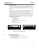
CIB Hardware Reference CTI Products, Inc. 5. Connectors Connectors The NETWORK IN/OUT ports on the front of the CIB are used to connect the CIB with other MCN modules. These ports carry both the network data signals as well as DC power for power distribution with other modules. Table 7 gives the pinout for these connectors. Figure 5 shows the location of pin 1 for each port. PRODUCTS, INC.
CIB Hardware Reference CTI Products, Inc. Connectors Signal VOTE Direction Input/Output RX DIS Input Input/Output FAIL MON Input Output Description Output activated to force vote a receiver. Comparator grounds input to indicate a voted receiver. Ground to indicate that a signal is being received. Output activated to disable a receiver. Ground input to indicate a disabled receiver. Ground input to indicate a failed receiver. Activated to force vote a receiver in the TAC and Ericsson / G.E.
CIB Hardware Reference CTI Products, Inc.
CIB Hardware Reference CTI Products, Inc.
CIB Hardware Reference CTI Products, Inc. 6. Mounting Mounting Various mounting kits are available to mount the CIB module. Mounting Kits Rack Mount - 4 A size modules 1 Rack Unit (1.75") High Rack Mount - 2 A size modules plus 1 B size module 1 Rack Unit (1.75") High (Used to mount 2 CIBs and 1 EXB module.) Wall Mount - 1 A size module Digitac Mounting Kit and Cable Mounts on rear of Digitac comparator. Includes "T" ribbon cable to connect to P805.
CIB Hardware Reference CTI Products, Inc.
CIB Hardware Reference CTI Products, Inc. 7. Comparator Wiring Lists Comparator Wiring Lists This section includes wiring lists to help you connect a CIB module to a particular comparator. If you are using a comparator not shown in this section, refer to Table 9 for the pinout of connector J1 on the back of the CIB module. NOTE: When connecting the CIB to your comparator, please follow the settings specified for jumpers E1A and E1B.
CIB Hardware Reference CTI Products, Inc. 7.
CIB Hardware Reference CTI Products, Inc.
CIB Hardware Reference CTI Products, Inc. 7.
CIB Hardware Reference CTI Products, Inc.
CIB Hardware Reference CTI Products, Inc. 7.
CIB Hardware Reference CTI Products, Inc.
CIB Hardware Reference CTI Products, Inc. 7.4 Comparator Wiring Lists M/A-Com / Ericsson / G.E. Analog Voter Wire TB1-TB6 or RX Mod Pins GE Sig.
CIB Hardware Reference CTI Products, Inc. Comparator Wiring Lists M/A-Com / Ericsson / G.E.
CIB Hardware Reference CTI Products, Inc. Comparator Wiring Lists 7.4.1 Voter Modifications For Receiver Module Fail Monitoring There is no isolated Fail signal brought out on the G.E. receiver module. The Fail signal on all modules are bussed together to provide a single Fail signal on the voter backplane. A field modification is required to bring out an isolated Fail line for each of the receiver modules.
CIB Hardware Reference CTI Products, Inc. 7.
CIB Hardware Reference CTI Products, Inc.
CIB Hardware Reference CTI Products, Inc. 7.5.1 Comparator Wiring Lists JPS Voter Modifications for Monitoring Voted Out using Channel Select In The JPS SNV-12 Voters with firmware version 1.08 or lower do not pull the Vote Out line to ground when a receiver channel is selected externally through the Select In lines (terminal 11). the Voted Out line goes low only when the SNV-12 votes the Receiver through the standard voting process. Votes are not indicated due to a force select input.
CIB Hardware Reference CTI Products, Inc. 7.
CIB Hardware Reference CTI Products, Inc.
CIB Hardware Reference CTI Products, Inc. 8. Module Error Codes Module Error Codes This section lists all CIB specific module error codes that can be displayed by a user interface (such as a PC’s display running MCNRCD). Error Code Description 80 The CIB is setup for transmitter monitoring and control (OPTION switch 3 is UP) but the CIB is not communicating with the TIB module. Verify that the TIB is connected to the MCN network and that it is properly configured to operate with this CIB.
CIB Hardware Reference CTI Products, Inc. 9. Troubleshooting Troubleshooting This table is a list of troubleshooting tips specific to the CIB module. For additional troubleshooting tips, refer to the troubleshooting section found in the Monitoring and Control Network System Manual, reference 1. Due to the high percentage of surface-mount components, the CIB is treated as a field replaceable unit.