
Manual


CHIB Hardware Reference Option Switches
CTI Products, Inc.
68-11662-100
6
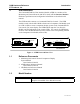
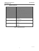
4.2 Rear Panel Switches
The rear panel switches are read by the CHIB only upon reset. The module must
be power cycled or reset after these switches are set so that the options will take
effect.
SWITCH MODULE DESCRIPTION DEFAULT
SER MODE
position 1
Reserved
Nust be Up
UP
position 2 Reserved
Must be Up
UP
GROUP
Hex Rotary
unit address setting
refer to text
Derived from Serial
Number -- See Text
MODULE
Hex Rotary
unit address setting
refer to text
Derived from Serial
Number -- See Text
OPTION B
position 1 baud rate select 0 (see Table 4) DOWN
position 2 baud rate select 1 (see Table 4) UP
position 3 baud rate select 2 (see Table 4) UP
position 4 Reserved DOWN
Table 3 - CHIB Rear Panel Option Switches
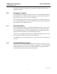
The Group and Module selector switches are used to set the unit address during
module installation. See the Address Setting section of this manual for more
information about setting these switches.
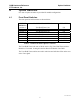
Baud Rate Option B
SW 1
baud rate select 0
Option B
SW 2
baud rate select 1
Option B
SW 3
baud rate select 2
9600 bps UP UP DOWN
14.4 kbps DOWN DOWN DOWN
19.2 kbps DOWN DOWN UP
38.4 kbps UP DOWN UP
57.6 kbps ** DOWN UP UP
115.2 kbps UP UP UP
Table 4 - Baud Rate Selector Switches
** Factory Default