Application Note Ctek Automation Control Application APN007 Release 4.02.02 Ctek – Things That Move Data .
5 July 2014 Contents TABLE OF FIGURES.........................................................................................................................................................IV INTRODUCTION: .............................................................................................................................................................. 1 THEORY OF OPERATION ..........................................................................................................................
25 July 2014 More About Digital Inputs and Outputs ..........................................................................................................................................24 Understanding The Input and Output Polarity Setting ........................................................................................................................ 24 Min/Max Range and Sensor Calibration: ..........................................................................................................
25 July 2014 Digital I/O – Set .................................................................................................................................................................................... 38 Numeric I/O – Set................................................................................................................................................................................. 39 Math functions.....................................................................................
25 July 2014 Table of Figures FIGURE 1 – THEORY OF OPERATION ................................................................................................................................................ 1 FIGURE 2 - TOP LEVEL NAVIGATION ............................................................................................................................................... 2 FIGURE 3 - AUTOMATION CONTROL CONFIGURATION MENU.............................................................................
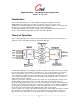
Application Note – Automation Control Application APN007 25 July, 2014 Introduction: Ctek's Automation Manager is an optional firmware application available for the Ctek Z4200/Z4400 series SkyRouter. It provides the logic and control necessary to create sophisticated automation applications that evaluate analog, digital, and pulse sensor inputs, and, based on sensor inputs, and programming logic, control output devices.
Application Note – Automation Control Application APN007 25 July, 2014 (digital), basic math functions (numeric), and can be assigned event thresholds. Virtual pins are useful to modify processing logic, store intermediate results, and to display values derive from programs. Just like physical pins virtual inputs are temporary while virtual outputs are persistent. Note – This document often refers to inputs and outputs as pins or input pins or output pins or virtual pins depending on their origin.
Application Note – Automation Control Application APN007 25 July, 2014 4. Configure outputs on each installed module 5. Create and assign formulas as required 6. Create and assign programs as required Once configuration has been completed the selections are deployed using the Execute New Configuration button. If logging is used the Logs selection can provide useful information about system operation and can also be used to debug sensor and output installations.
Application Note – Automation Control Application APN007 25 July, 2014 User Interface and Configuration Specifics Selecting the Automation Control Configuration item presents the following menu from which the user can install, configure, and adjust settings on I/O modules and sensors. Note: System Errors indicates entries made as a result of this application since the last time the box was restarted.
Application Note – Automation Control Application APN007 25 July, 2014 Figure 4 - Unit Configuration Location Name: A descriptive name assigned to this controller and its associated I/O modules 5
Application Note – Automation Control Application APN007 25 July, 2014 SMS Remote Control: Enable or disable SMS read/write control/monitoring of automation control I/O pins. (Introduced in release 4.2 – see TechNote TN009 for details) Authorized Phone Numbers: A list of between 0 and 5, 10-digit, space separated phone numbers that are permitted to use the SMS Remote Control feature. A blank field blocks all phone numbers. The * (star) character allows any number.
Application Note – Automation Control Application APN007 25 July, 2014 Authentication and SSL Encryption: Settings specific to each email SMTP server. Display Group Names: User assigned names of logical groupings of inputs and outputs that will be used to organize the display of the Control Panel. Both inputs and outputs can be organized under a single group name.
Application Note – Automation Control Application APN007 25 July, 2014 ABOUT I/O M ODULE ADDRESSING I/O module part numbers B1204S (4-port relay), B1216S (16-port) and Z1216S use RS485 communications. A default address of 99 is assigned to these modules when they leave the factory. Their addresses may be reassigned under program control from the replace function under the Configure I/O Modules screen. To readdress these modules first add them (Add function) as module address 99.
Application Note – Automation Control Application APN007 25 July, 2014 Figure 7 - Module Delete Screen Replace: The replace function has three purposes. First it is used to replace an existing module with a spare. Secondly it can be used to readdress an existing module. In either case all settings associated with that module will be preserved. When selected the Replace Module screen will be displayed as shown in Figure 8.
Application Note – Automation Control Application APN007 25 July, 2014 Note: The default commend described above uses a broadcast that will set the address of all physical modules to 99. You may want to disconnect modules from the line up that do not require their address to be resored to default. Disable Disabling a module removes it from the communications routine. All set up information for the disabled module remains intact.
Application Note – Automation Control Application APN007 25 July, 2014 Configure Outputs A representative portion of the Configure Outputs navigation screen is shown below. This is a selection screen. Use the Type pull-down and Edit button to select a specific Output for edit. To completely disable an output select Disabled in the pull-down and then press the associated edit button. The default display shows the current status of outputs across all modules.
Application Note – Automation Control Application APN007 25 July, 2014 Output Configuration Screens Figures 8 – 11 below show the configuration screens for the supported output types, physical/digital, virtual/digital, and virtual/numeric. Following the screen images is a complete list of attributes found on these screens and a description of their application on a specific type of pin.
Application Note – Automation Control Application APN007 25 July, 2014 Figure 14 - Output Virtual/Numeric 13
Application Note – Automation Control Application APN007 25 July, 2014 Pin Name Pin Type Output Name All Local Display Cloud Display Log Program Initial Value Label for On[Off] Output State Shutoff Timer Polarity Decimal Scale Current Value Initial Value (numeric) Description Assigns a name to the output pin that will be used in display, logging, and alarms All Assigns the pin to a specific panel within the control panel display.
Application Note – Automation Control Application APN007 25 July, 2014 Configure Inputs This is a selection screen. Use the Type pull-down and Edit button to select a specific Input for edit. To completely disable an Input select Disabled in the pull-down and then press the associated edit button. The default display shows the current status of Inputs across all modules.
Application Note – Automation Control Application APN007 25 July, 2014 Figure 17- Input Physical/Digital Figure 18 - Input Physical/Analog 16
Application Note – Automation Control Application APN007 25 July, 2014 Figure 19 - Input Physical/Pulse Figure 20 - Input Virtual/Digital 17
Application Note – Automation Control Application APN007 25 July, 2014 Figure 21 - Input Virtual/Numeric 18
Application Note – Automation Control Application APN007 25 July, 2014 Input Pin Name Pin Type Description Key: PD = Physical Digital, PA = Physical Analog, PP = Physical Pulse VD = Virtual Digital, VN = Virtual Numeric VD = Virtual Digital, VN = Virtual Numeric Input Name Display All All Assigns a name to the Input pin that will be used in display, logging, and alarms Assigns the pin to a specific panel within the control panel display. Set to Off for pins that will not be displayed on control panel.
Application Note – Automation Control Application APN007 25 July, 2014 Alarm PA, PP, VN Alarm Repeat PA, PP, VN Repeat Rate PA, PP, VN Program PA, PP, VN Program Repeat PA, PP, VN Repeat Rate (program) PA, PP, VN Formula PA, VN Polarity Label For On[Off] PD, VD PD, VD Input Source (Digital) PD, VD On[Off] Alarm PD, VD On[Off] Alarm Repeat PD, VD On[Off] Repeat Rate PD, VD On[Off] Program PD, VD On[Off] Program Repeat PD, VD On[Off] Repeat Rate PD, VD Min[Max] Range PA On/Off
Application Note – Automation Control Application APN007 25 July, 2014 Min[Max] Units PA Correction PA Multiplier PP Interval PP Input Source (Numeric) VN Initial Reference (Numeric) PA, PP, VN Initial Value (Numeric) PA, PP, VN Decimal Scale VN somewhat smaller than the theoretical due to sensor characteristics and minor variations in the reference voltage. This is a quantitative value for the low end of the expected engineering value measurement of this sensor.
Application Note – Automation Control Application APN007 25 July, 2014 Digital Input Pins – Source of Inputs Figure 23 - Input Sources (Digital) Digital input pins can receive inputs from themselves, any other digital input or output pin, or the following internal sources listed in the table below. Up to four input sources can be combined using the boolean operator AND or the boolean operator OR. All input processing is completed before the pin is evaluated.
Application Note – Automation Control Application APN007 25 July, 2014 Numeric Input Pins – Source of Inputs Figure 25 - Input Sources Numeric Analog or numeric input pins can receive inputs from themselves, any other numeric input or output pin, or the following internal sources listed in the table below. A formula assigned to a pin will be processed before the pin is evaluated.
Application Note – Automation Control Application APN007 25 July, 2014 Input Definitions – Virtual Numeric Inputs Any Physical or Virtual Input pin * Any Physical or Virtual pin* Input voltage to the SkyRouter Internal Temperature of SkyRouter - C Internal Temperature of SkyRouter - F Signal Strength of cellular signal Latitude measured by internal GPS Longitude measured by internal GPS Speed measured by internal GPS Course measured by internal GPS System error count as senses by Automation Sys Errors Cont
Application Note – Automation Control Application APN007 25 July, 2014 Min/Max Range and Sensor Calibration: Range refers to the range or precision of the analog to digital (A/D) conversion. Ctek 1216 I/O modules provide 12 bit conversion resulting in a theoretical 4096 discrete values, 0 - 4095. Ctek I/O modules start with a range offset of 7 making the theoretical available range 7 - 4095.
Application Note – Automation Control Application APN007 25 July, 2014 Analog Input Processing Figure 27 - Analog Input Processing Thresholds There are three key concepts to understand about thresholds. The first is to recognize that thresholds have a directional component, meaning that each threshold is defined in terms of a less than or greater than modifier.
Application Note – Automation Control Application APN007 25 July, 2014 boundaries of an operating range that would otherwise be in conflict with level sensitive thresholds. The diagram and tutorial following demonstrates this application. The last key concept is the order in which thresholds are evaluated. This is critical because thresholds MUST be defined on the input screen in the order that they will be evaluated.
Application Note – Automation Control Application APN007 25 July, 2014 Pulse Input - Latching The setting Greater Than Latch Function is a special case unique to the pulse input. It is designed to be used to capture and execute upon single pulse type inputs that have the possibility of recurring. A typical use of this type of input is to capture (latch) the depression of a momentary switch. When set with a value of 0.00 it will launch its assigned program each time the switch is pressed to cause a pulse.
Application Note – Automation Control Application APN007 25 July, 2014 Configure Formulas Ctek's Automation Control application provides support for user defined formulas that can be applied to analog and numeric inputs. Formulas are applied as a part of the input processing prior to the pin being evaluated. A standard conversion formula is released with the firmware. In many cases this standard formula will suffice for input processing.
Application Note – Automation Control Application APN007 25 July, 2014 Figure 30 - Edit Input Formula Operands Current Input Pin: Selects the input value provided by the pin to which the formula is attached as an operand Other Input Pin: Selects the value on the input pin referenced in the right hand column Output Pin = Selects the value on the output pin referenced in the right hand column Constant Value = Use the constant entered in the center column as the next operand Correction: The correction value
Application Note – Automation Control Application APN007 25 July, 2014 Max – Min Units: The value (Maximum Units - Minimum Units) becomes the next operand (fn) Average Memory 1 and (fn) Average Memory 2 Both functions do the same thing but each can only be used by one pin so the 2 environments allow for a total of 2 averaging inputs. These are functions are performed on the value in the X register with the results being returned to the X register.
Application Note – Automation Control Application APN007 25 July, 2014 Figure 31 - Standard Conversion Formula The standard conversion formula shown above reads the sensors input value and subtracts from it the minimum range value assigned to the sensor. It then divides the resulting value by the value of (Max - Min Range). The resulting number is then multiplied by the value of (Max - Min Units) and also by the correction value assigned.
Application Note – Automation Control Application APN007 25 July, 2014 Programs Programs are named groups of functions that can be applied to a specific input or output as the result of a threshold event or level occurring on an input or virtual output. For instance, a program called Power Indicator OFF (9) could be used to turn on an indicator whenever charging power is removed from a battery powered system. The same program could also set the application status to yellow or 1 for display on VDDNS.
Application Note – Automation Control Application APN007 25 July, 2014 Figure 33 – Program Edit Screen Program Edit Fields Program Name The user defined name assigned to this program Action The action field provides a pull-down menu of the different functions that can be executed by this program. Parameters The parameters field contains values that the program will operate upon. Parameters MUST be space separated.
Application Note – Automation Control Application APN007 25 July, 2014 Log and Logging Set Up and Management The Automation Control application maintains a log file of events and thresholds in near real time as they occur. Logging is enabled on the unit configuration screen. The unit configuration also allows the user to specify the frequency at which they wish to receive log files and the frequency at which events will be logged.
Application Note – Automation Control Application APN007 25 July, 2014 The Control Panel The Control Panel for the Automation Control provides a consolidated view of selected inputs and outputs that have been selected for display in their specific configuration. The control panel also provides On/Off buttons for digital outputs and a data entry field for numeric outputs. Inputs are always displayed as read only..
Application Note – Automation Control Application APN007 25 July, 2014 Figure 35 - Sample Control Panel Display 37
Application Note – Automation Control Application APN007 25 July, 2014 Appendix A – Function Library Functions are predefined building blocks used to build user defined programs. Parameters or arguments to the functions must be separated by a single space. The following is the current list of functions available for creating user programs: Following the function list is a detailed description of each individual function.
Application Note – Automation Control Application APN007 25 July, 2014 Parameters = o 6 u 1 Numeric I/O – Set Numeric I/O – Set P1 P2 P3 P4 P1 and P2 define the destination that is being set while P3 and P4 define the source P1 = i for input or o for output (Must be numeric) P2 = pin number (Must be numeric) P3 = i for input, o for output or u for user defined value P4 = pin number or user defined value Example: Setting numeric input pin 12 to the value of numeric output pin 9 Action: Numeric I/O – Set P
Application Note – Automation Control Application APN007 25 July, 2014 Note on Remote Commands Remote operations are those decisions and resulting actions that are distributed between two or more SkyRouters in different physical locations connected over the cellular network. This release contains a significant simplification of remote operations.
Application Note – Automation Control Application APN007 25 July, 2014 Timer/Counter – Start [Note – Changed In Release 4.02.02] Timer/Counter – Start P1 P2 P3 P4 P5 P6 P7 P8 P9 P1 = i for input or o for output (numeric) P2 = pin number. This is where the timer value lives (numeric) P3 = counter type.
Application Note – Automation Control Application APN007 25 July, 2014 Timer/Clock – Start P1 P2 P3 P4 P5 P6 P7 P1 = i for input or o for output (digital) P2 = pin number. This is where the clock is generated (digital) P3 = i for input, o for output or u for user defined value P4 = pin number or user defined clock rate value P5 = update rate (int) in 0.1 second increments. How often start value will be decremented. P6 = update value (float). How much will be decremented from P4 for each update period.
Application Note – Automation Control Application APN007 25 July, 2014 Timer/Alarm Override – Start [Note – Changed In Release 4.02.02] cP1 P2 P3 P4 Timer/Alarm Override – Start provides a mechanism to override (disable) all alarms for a specified (in minutes) period of time. P1 and P2 define the pin that will represent the state of override, and P3 and P4 define the period of time for which alarms will be disabled.
Application Note – Automation Control Application APN007 25 July, 2014 d) All hour timers (defined by P5) must be housed in outputs. The value of P5 will be interpreted as an output. Motor Group Control Allows up to four motors to be controlled in a group where primary responsibility will alternate to ensure wear leveling. Hours of operation will be tracked in hours and tenths of hours.
Application Note – Automation Control Application APN007 25 July, 2014 Application Status – Set [Note – New In Release 4.02.02] Application Status – Set provides a queuing and prioritization mechanism for Automation Control events/thresholds/states (Alarm States) that wish to change the application status color of the pin indicating the units position on the SkyCloud display. Between 1 and 10 different pins, each capable of changing the display to red, yellow, or green can be managed.
Application Note – Automation Control Application APN007 25 July, 2014 Action: Application Status – Set Parameters: 5 0 6 A NOTE – Force status update (P2 = 3) is a special case. It does not require a corresponding Alarm – Clear program and can use the P1, P3,and P4 values of any the application. For the two examples above a force status update could be issued using any of the examples below to achieve the same results.