
Instruction manual


CTA Instruction Manual MPE
Reference: MT0027DA This document may be modified without prior notice 19
Revision date: 11/05/06 Even partial reproduction is prohibited without authorisation in writing
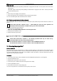
14 Circuit diagrams
14.1 Refrigeration/pneumatic circuit diagram (SC0014A)
Label Components 006-020 025-125
AO Compressed air exhaust
∏ ∏
AI Compressed air inlet
∏ ∏
CD Condensing unit
∏ ∏
CF Condensate filter
∏ ∏
CO Condensate discharge
∏ ∏
CP Compressor
∏ ∏
CS Condensate separator
∏ ∏
CT Capillary tube
∏ ∏
OF DTM
®
heat exchanger
∏ ∏
DF Dehydrator filter
∏ ∏
EB Electronic board
∏ ∏
F Fan
∏ ∏
FPS Fan Pressure switch
∏
HPS High pressure switch
∏ ∏
LPS Low pressure switch
∏
MV Manual valve
∏ ∏
RS Probe regulation
∏ ∏
SV Solenoid purge valve
∏ ∏
HPS
CD
F
CP
DF
FPS
LPS
j
°
°
ζ
ζ
EB
CS
MV
DE
SV
CF
CT
RS
ζ
AO
AI
CO