
User's Manual
CSI-Wireless LoCate-001 Users Manual
Revision 1.0 Page 15 6/11/2001
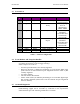
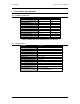
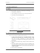
3.5.3 External Connector Pin Assignments
The external I/O connector pin assignments are as follows:
Connector: Molex 53259-1310 or equivalent
Mating connector, for customer-supplied cable harness: Molex 51067-1300 or equivalent
Pin Description Notes
1 Relay Driver 1 Connects relay coil to ground, other side of relay coil goes to supply positive.
2 Relay Driver 2 Connects relay coil to ground, other side of relay coil goes to supply positive.
3 Digital Output 1 0 and 5 volt logic signal with 2 KOhm series impedance driven from LoCate-
001
4 Digital Output 2 0 and 5 volt logic signal with 2 KOhm series impedance driven from LoCate-
001
5 Digital Input 1 0 and 5 volt logic signal with 300 KOhm to ground as input to LoCate-001
6 Digital Input 2 0 and 5 volt logic signal with 300 KOhm to ground as input to LoCate-001
7 Analog Input Input for measurement, -0.3 volts to 7 volts
8 Ground Connects to chassis of LoCate-001
9 Serial Output Signal from LoCate-001 to Computer
10 Serial Input Signal from Computer to LoCate-001
11 Reserved Reserved for factory use
12 5 Volt Reference 5 volts with 2 KOhm series impedance, for reference use
13 Battery Voltage For measurement only, 0 to 20 volts range.
Table 14 - External Signal Connector
Note:
Pin 1 is located next to larger connector (TNC)
Pin 13 is located next to smaller connector (SMA).
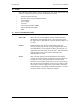
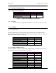
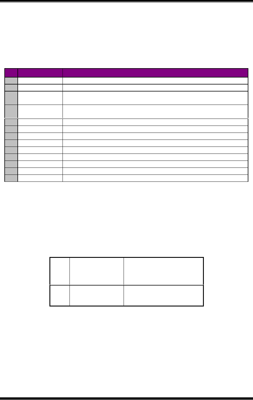
3.5.4 Power Lead Assignments
The LoCate-001 power lead assignments are as follows:
Black Supply Battery
Voltage Negative
Power input to Locate, battery
negative with protection for
current to chassis, connected to
chassis with low impedance.
Red Supply Battery
Voltage Positive
Power input to Locate, 8 to 18
volts, 2 amp fused externally,
internally protected.
Table 15 - Power Supply Lead Use.