
User Manual
Asset-Link 4XX User Manual May 10, 2004
970-00047 Rev. 1.0
CSI Wireless©2004 Specifications subject to change without notice Page v
Table of Contents
1 INTRODUCTION.............................................................................................1-8
1.1 P
URPOSE
..........................................................................................................1-8
1.2 S
COPE
..............................................................................................................1-8
1.3 A
SSET
-L
INK
P
RODUCT
N
UMBERING
................................................................1-8
1.4 R
EFERENCED
D
OCUMENTS
..............................................................................1-9
1.4.1 CSI-Wireless documents:...................................................................... 1-9
1.4.2 Public Documents or Standards ............................................................ 1-9
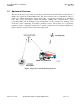
1.5 O
PERATIONAL
O
VERVIEW
.............................................................................1-10
1.6 S
YSTEM
P
RODUCT
F
EATURES
........................................................................1-11
2 PRODUCT DESCRIPTION .............................................................................2-1
2.1 D
ETAILED
S
YSTEM
D
ESCRIPTION
....................................................................2-1
2.2 M
ECHANICAL
D
IMENSIONS
.............................................................................2-2
2.3 GPS R
ECEIVER
................................................................................................2-2
2.3.1 GPS Position/Velocity Fix .................................................................... 2-2
2.4 F
UNCTION
C
ONTROL
P
ROCESSOR
....................................................................2-4
2.4.1 Non-Volatile Memory........................................................................... 2-4
2.4.2 FCP Operating Modes........................................................................... 2-5
2.4.2.1 FCP Sleep Mode Operation.............................................................2-6
2.4.2.2 Active Mode ....................................................................................2-7
2.4.2.3 Full-Power Mode.............................................................................2-9
2.4.3 Power Off Mode.................................................................................. 2-10
2.4.4 Connection and Configuration ............................................................ 2-10
2.5 P
OWER
M
ANAGEMENT
..................................................................................2-11
2.5.1 Power Input Protection........................................................................ 2-11
2.5.2 MicroBurst™, Control Channel Data ................................................. 2-11
3 APPLICATION I/O CONNECTOR SPECIFICATIONS ................................3-1
3.1 A
PPLICATION
I/O C
ONNECTOR
T
YPE AND
P
INOUT
..........................................3-1
3.2 P
OWER
I
NPUT
S
PECIFICATIONS
........................................................................3-2
3.2.1 Power Requirements ............................................................................. 3-2
3.2.2 Power Consumption Profile .................................................................. 3-2
3.2.3 Grounding “Precautions” ...................................................................... 3-2
3.2.4 Ground Wire Size.................................................................................. 3-3
3.2.5 Grounding Voltages .............................................................................. 3-3
3.2.6 Power Supply Over Voltage Protection ................................................ 3-3
3.2.7 Power Supply Reverse Voltage Protection ........................................... 3-3
3.2.8 Power Supply Decay to Zero Volts....................................................... 3-3
3.2.9 Power Supply Engine Start Disturbances ............................................. 3-4
3.2.10 Power Supply Connector ESD.............................................................. 3-4
3.2.11 Power Supply Connector Load Dump .................................................. 3-5
3.3 R
ELAY
D
RIVER
S
PECIFICATIONS
.....................................................................3-6
3.4 A
NALOG TO
D
IGITAL
C
ONVERTER
I
NPUTS
......................................................3-6