
User Manual

Asset-Link 4XX User Manual May 10, 2004
970-00047 Rev. 1.0
CSI Wireless©2004 Specifications subject to change without notice Page 4-1
4 AMPS/GSM Connector Specifications
The cellular connector is either a standard right angle male FAKRA SMB connector.
The shell of the connector is connected to the Asset-Link ground. The center pin of
the connector is for the AMPS Cellular Class III or GSM transceiver input and output
at 50 ohms nominal impedance.
The AMPs/GSM cellular connector is designed to be connected to an antenna of less
than 3 dBd gain, to meet safety standards. Refer to the warnings in the cellular
antenna accessories section.
The cellular or GSM module is selected by a passive relay contact internal to the
T4000. When one module is connected, the other module is disconnected. The relay is
a latching type, so it will remain in the position for the last selected radio module
even when all power is removed.
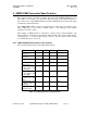
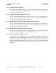
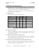
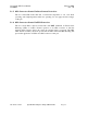
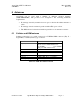
4.1.1 AMPs/GSM Cellular Interface Specification
The cellular interface has the following characteristics:
Parameter Min Nominal Max Units
825-894 MHz &
Impedance
30 50 85 Ohms
1850-1970 MHz
Impedance
26 50 95
825-
894 MHz Return
Loss
12 15 Inf DB
1850 –
1970 MHz
MHz Return Loss
10 12 Inf DB
Maximum RF
voltage applied 850
to 900 MHz
-- -- -30 DBm
Maximum RF
voltage applied 1850
to 1970 MHz
-- -- -30 DBm
Maximum RF signal
available 82
0 to 850
MHz
-- -- 33 DBm
Maximum RF signal
available 1850 to
1910 MHz
-- -- 30 DBm
Impedance to
Ground at D.C.
10K 10M Inf Ohms
Table 4-1 Cellular Interface Characteristics