
User Manual
Asset-Link 4XX User Manual May 10, 2004
970-00047 Rev. 1.0
CSI Wireless©2004 Specifications subject to change without notice Page 3-3
ground. Do not use the same grounding terminal for this connection as for both wires
leading from pins 24 and 12. The use of two connections to the vehicle negative is a
safety feature, and using only one terminal will negate that safety feature.
Do not attempt to use the grounding braid on the FAKRA SMB connector as a
grounding method as removal of these connectors will remove the Asset-Link chassis
grounding. Do not ground the antenna outside braid to areas that will have significant
current flows that would go through the braid and into the Power Supply Negative
line.
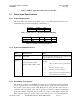
3.2.4 Ground Wire Size
The wire size for this connection should be a minimum of 20 gauge, with 18 gauge
recommended.
3.2.5 Grounding Voltages
Ensure that the voltage drop on this line to the reference point for the serial, digital
and analog inputs/outputs is less than the voltage margin or allowable error. Note that
the serial port line connects to this ground, and that high-speed impulses or high
frequency noise allowed between the Asset-Link chassis and the vehicle/serial unit
reference point will appear as noise on these lines.
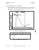
3.2.6 Power Supply Over Voltage Protection
The Asset-Link will survive a Power Supply Voltage rise above 36 volts up to 50
volts without damage. Voltages above 50 volts for long may cause the Power Supply
current to rise above the internal power input fuse. The appropriate SAE J1211
specification is per table 2 “Battery Electrolyte Boil-Off. Recovery of Asset-Link
operation may require fuse replacement.
3.2.7 Power Supply Reverse Voltage Protection
The Asset-Link will not be damaged by connection of the Power Supply Connector
Negative (DB-25 pins 12 & 24) to the vehicle positive if the voltage is within the
normal voltage limits. Removal of the incorrect connection is needed for correct
operation.
The Asset-Link will not be damaged by connection of the Power Supply Connector
Positive (DB-25 pins 13 & 25) to a vehicle voltage that is negative with respect to the
Power Supply Connector Negative (DB-25 pin 12 & 24) if the voltage is within the
normal voltage limits. Removal of the incorrect connection is needed for correct
operation.
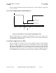
3.2.8 Power Supply Decay to Zero Volts
The Asset-Link will survive a decay of voltage down to zero volts from the minimum
voltage of 7.2 (±.2V) volts. Below 7.2 volts, or a programmable limit the Asset-Link
will enter the Sleep mode and draw less than 35 microamperes until the voltage drops
below 5.5volts at which time the device will shut Off completely.