
User Manual

Asset-Link 4XX User Manual May 10, 2004
970-00047 Rev. 1.0
CSI Wireless©2004 Specifications subject to change without notice Page 2-5
2.4.2 FCP Operating Modes
The following description of the four operating modes and power management is a
very general description of the Asset-Link programming. Application providers can
and should develop their own specific configuration to maximize connectivity and
minimize battery consumption. Developers can use meters, voltage thresholds, I/Os,
actions, exceptions and schedules to create unique applications by the PDI commands
available through the AVL 2004 program. There are four major states for the FCP:
1. No Power
2. Sleep
3. Active
4. Full Power
Each may be invoked in response to exceptions that are logically combined with
either I/O inputs and/or voltage level of power resources. To create such a
configuration, the reader should refer to the AVL 2004 User Manual (970-00050).
Each of these states has specific power consumption and abilities, which are detailed
in the later sections of this manual.
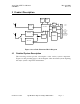
Figure 3 shows the various power modes and operational states. Switching between
modes (or states) can be determined by singular, or combination events. (It must be
noted that some of these events can act in concert, in an additive manner, while others
are normally set to act alone, and still others are dominant over another). The I/O
controller monitors a majority of the bus activity (including serial and analog inputs)
using an I/O timer. The I/O timer is set following the detection of an activity at the
I/O ports. The I/O timer can also be set by a configurable action group. Both of these
monitoring events maximizes the potential for the FCP to remain in the sleep mode
and thus conserve power. The following are routinely monitored by the FCP:
• Activity on I/O controller or the FCP serial port
• Changing of the voltage of the power supply as measured at the main input of
the device, to a configurable threshold
• Expiration of the GPS warm-up timer, GPS fix Duration timer and Ears-On
timer. Ears-On timer is set when the cellular module is turned ON by a
configurable action group of an exception. The GPS timers are configurable
GPS parameters and are set when turning ON GPS receiver.
• Schedule keeping
• Active Elapsed timers that run over the threshold
• Exceptions that call Full-Power action
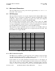
The following parameters relating to mode transition are configurable in the
hardware. AVL-2004 (see AVL 2004 User Manual 970-00050), the configuration
development tool, provides the usable value for each setting:
V
SUPPLY
Hi to Lo and Lo to Hi threshold Configurable 0 to 26 Volts